Nissan Rogue Service Manual: Sensor power supply2 circuit
Description
ECM supplies a voltage of 5 V to some of the sensors systematically divided into 2 groups, respectively.
Accordingly, when a short circuit develops in a sensor power source, a malfunction may occur simultaneously in the sensors belonging to the same group as the short-circuited sensor.
Sensor power supply 1
- APP sensor 1
- CKP sensor (POS)
- Intake manifold runner control valve position sensor
- Refrigerant pressure sensor
- TP sensor
NOTE: If sensor power supply 1 circuit is malfunctioning, DTC P0643 is displayed.
Sensor power supply 2
- APP sensor 2
- CMP sensor (PHASE)
- EVT control position sensor
- EOP sensor
- MAF sensor
Diagnosis Procedure
1.CHECK APP SENSOR 2 POWER SUPPLY CIRCUIT-1
- Turn ignition switch OFF.
- Disconnect accelerator pedal position (APP) sensor harness connector.
- Turn ignition switch ON.
- Check the voltage between APP sensor harness connector and ground.
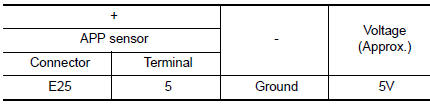
Is the inspection result normal? YES >> INSPECTION END
NO >> GO TO 2.
2.CHECK APP SENSOR 2 POWER SUPPLY CIRCUIT-2
- Turn ignition switch OFF.
- Disconnect ECM harness connector.
- Check the continuity between APP sensor harness connector and ECM harness connector.
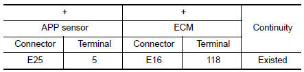
Is the inspection result normal? YES >> GO TO 3.
NO >> Repair open circuit.
3.CHECK SENSOR POWER SUPPLY 2 CIRCUIT
- Disconnect following sensors harness connector.
- Check harness for short to power and short to ground, between the following terminals.
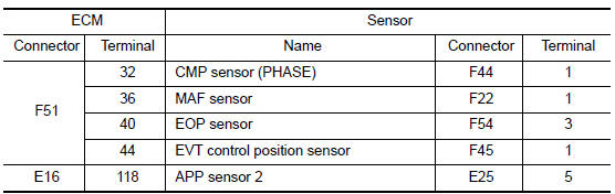
Is the inspection result normal? YES >> GO TO 4.
NO >> Repair short to ground or short to power in harness or connectors.
4.CHECK COMPONENTS
Check the following.
- APP sensor 2 (Refer to EC-444, "Component Inspection".)
- Camshaft position sensor (PHASE) (Refer to EC-300, "Component Inspection (Camshaft position sensor)".)
- EVT control position sensor (Refer to EC-387, "Component Inspection".)
- EOP sensor (Refer toEC-360, "Component Inspection".)
- MAF sensor (Refer to EC-200, "Component Inspection".)
Is the inspection result normal? YES >> Refer to GI-41, "Intermittent Incident".
NO >> Replace malfunctioning component.
 Refrigerant pressure sensor
Component Function Check
1.CHECK REFRIGERANT PRESSURE SENSOR FUNCTION
Start engine and warm it up to normal operating temperature.
Turn A/C switch and blower fan switch ON.
...

Other materials:
Cooler pipe and hose
Exploded View
Condenser
High-pressure flexible hose
Low-pressure flexible hose
Low-pressure pipe
Heating and cooling unit assembly
High-pressure pipe
Compressor
O-ring
Low-pressure service port
High-pressure service port
LOW-PRESSURE PIP
LOW-PRESSURE P ...
System
WARNING CHIME SYSTEM
WARNING CHIME SYSTEM : System Description
SYSTEM DIAGRAM (WITH INTELLIGENT KEY SYSTEM)
SYSTEM DIAGRAM (WITHOUT INTELLIGENT KEY SYSTEM)
COMBINATION METER INPUT/OUTPUT SIGNAL (CAN COMMUNICATION SIGNAL)
Input signal
Output signal
BCM INPUT/OUTPUT SIGNAL (CAN ...
Symptom diagnosis
SQUEAK AND RATTLE TROUBLE DIAGNOSES
Work Flow
CUSTOMER INTERVIEW
Interview the customer if possible, to determine the conditions that exist
when the noise occurs. Use the Diagnostic
Worksheet during the interview to document the facts and conditions when the
noise occurs and any
custome ...
