Nissan Rogue Service Manual: Cooler pipe and hose
Exploded View
- Condenser
- High-pressure flexible hose
- Low-pressure flexible hose
- Low-pressure pipe
- Heating and cooling unit assembly
- High-pressure pipe
- Compressor
- O-ring
- Low-pressure service port
- High-pressure service port
LOW-PRESSURE PIP
LOW-PRESSURE PIPE : Removal and Installation
REMOVAL
- Discharge the refrigerant. Refer to HA-23, "Recycle Refrigerant".
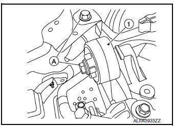
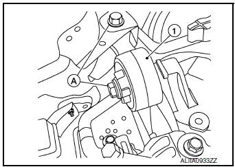
- Remove bolts (A) and engine upper mount (1).
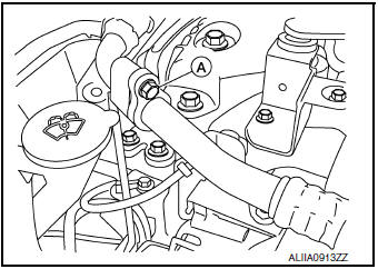
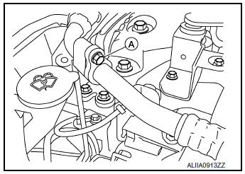
- Remove the bolt (A) that retains the low-pressure flexible hose to the low-pressure pipe.
CAUTION: Cap or wrap the joint of the pipe with suitable material such as vinyl tape to avoid the entry of air.
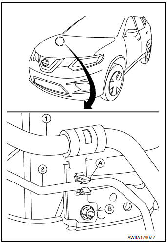
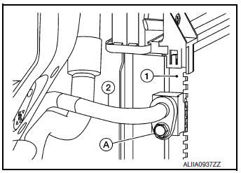
- Remove low-pressure pipe bracket bolts (A) and bracket.
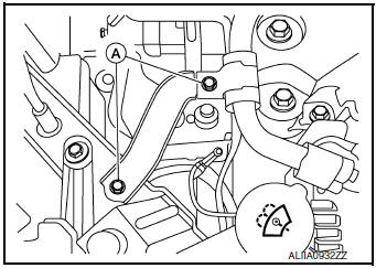
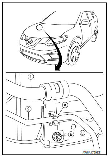
- Release high-pressure pipe (2) from clamp (A).
- Remove nut (B) and low-pressure pipe (1).
- Remove the bolt (A) that retains the low-pressure and high-pressure pipe to the expansion valve (1).
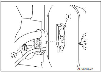
- Remove low-pressure pipe.
INSTALLATION
Installation is in the reverse order of removal.
CAUTION:
- Tighten bolts to specified torque. Refer to HA-32, "Exploded View".
- Do not reuse O-rings.
- Apply A/C oil to new O-rings for installation.
- After charging refrigerant, check for leaks. Refer to HA-21, "Leak Test".
LOW-PRESSURE FLEXIBLE HOSE
LOW-PRESSURE FLEXIBLE HOSE : Removal and Installation
REMOVAL
- Discharge the refrigerant. Refer to HA-23, "Recycle Refrigerant".
- Remove the bolt (A) that retains the low-pressure flexible hose to the low-pressure pipe.
CAUTION: Cap or wrap the joint of the pipe with suitable material such as vinyl tape to avoid the entry of air.
- Remove the nut (A) that retains the low-pressure flexible hose to the compressor.
- Remove the low-pressure flexible hose.
INSTALLATION
Installation is in the reverse order of removal.
CAUTION:
- Tighten nut/bolt to specified torque. Refer to HA-32, "Exploded View".
- Do not reuse O-rings.
- Apply A/C oil to new O-rings for installation.
- After charging refrigerant, check for leaks. Refer to HA-21, "Leak Test".
HIGH-PRESSURE PIPE
HIGH-PRESSURE PIPE : Removal and Installation
REMOVAL
- Discharge the refrigerant. Refer to HA-23, "Recycle Refrigerant".
- Remove front bumper fascia. Refer to EXT-17, "Removal and Installation".
- Remove air duct assembly. Refer to EM-24, "Exploded View".
- Remove bolts (A) and upper engine mount (1).
- Release high-pressure pipe (2) from clamp (A).
(1): Low-pressure pipe
(B): Nut
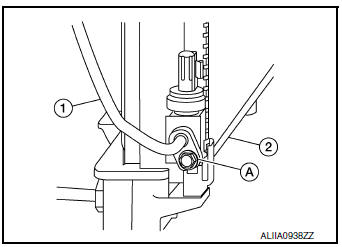
- Remove bolt (A) that retains high-pressure pipe (1) to the condenser
(2).
CAUTION: Cap or wrap the joint of the pipe with suitable material such as vinyl tape to avoid the entry of air.
- Remove the bolt (A) that retains the high-pressure and low-pressure pipe to the expansion valve (1).
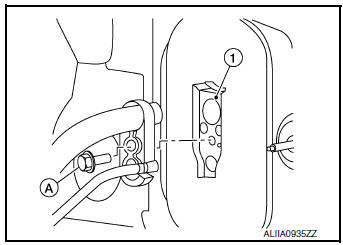
- Remove high-pressure pipe.
INSTALLATION
Installation is in the reverse order of removal.
CAUTION:
- Tighten bolts to specified torque. Refer to HA-32, "Exploded View".
- Do not reuse O-rings.
- Apply A/C oil to new O-rings for installation.
- After charging the refrigerant, check for leaks. Refer to HA-21, "Leak Test".
HIGH-PRESSURE FLEXIBLE HOSE
HIGH-PRESSURE FLEXIBLE HOSE : Removal and Installation
REMOVAL
- Discharge the refrigerant. Refer to HA-23, "Recycle Refrigerant".
- Remove front bumper fascia. Refer to EXT-17, "Removal and Installation".
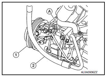
- Remove the bolt (A) that retains the high-pressure flexible hose (2) to the condenser (1).
CAUTION: Cap or wrap the joint of the pipe with suitable material such as vinyl tape to avoid the entry of air.
- Remove the bolt (A) that retains the high-pressure flexible hose (2) to the compressor (1).
INSTALLATION
Installation is in the reverse order of removal.
CAUTION:
- Tighten bolts to specified torque. Refer to HA-37, "Exploded View".
- Do not reuse O-rings.
- Apply A/C oil to new O-rings for installation.
- After charging the refrigerant, check for leaks. Refer to HA-21, "Leak Test".
 Compressor
Exploded View
Compressor
Removal and Installation
REMOVAL
Discharge the refrigerant. Refer to HA-23, "Recycle Refrigerant".
Remove the engine under cover. Refer to EX ...
 Condenser
Exploded View
Air guide (LH)
Condenser upper bracket (LH)
Condenser (includes liquid tank)
Condenser upper bracket (RH)
Air guide (RH)
Refrigerant pressure sensor
C ...
Other materials:
SRS air bag warning lamp does not turn on
AIR BAG Warning Lamp Does Not Turn On
1.CHECK METER FUSE
Check the 10A fuse [No. 13, located in the fuse block (J/B)].
Is the fuse blown?
YES >> GO TO 2.
NO >> GO TO 3.
2.REPLACE METER FUSE AND CHECK AGAIN
Replace 10A fuse [No. 13, located in the fuse block (J/B)] and turn ign ...
C1704, C1705, C1706, C1707 low tire pressure
DTC Logic
NOTE:
The Signal Tech II Tool [- (J-50190)] can be used to perform the following
functions. Refer to the Signal Tech II
User Guide for additional information.
Activate and display TPMS sensor IDs
Display tire pressure reported by the TPMS sensor
Read TPMS DTC ...
Voice commands
You can use voice commands to operate various
Bluetooth® Hands-Free Phone System features
using the NISSAN Voice Recognition system. For
additional information, refer to “NISSAN Voice
Recognition System” in this section.
Voice Prompt Interrupt
While using the Voice Recognition system, the ...
