Nissan Rogue (T33) 2021-Present Service Manual: Removal and Installation :: Back Door
Exploded View
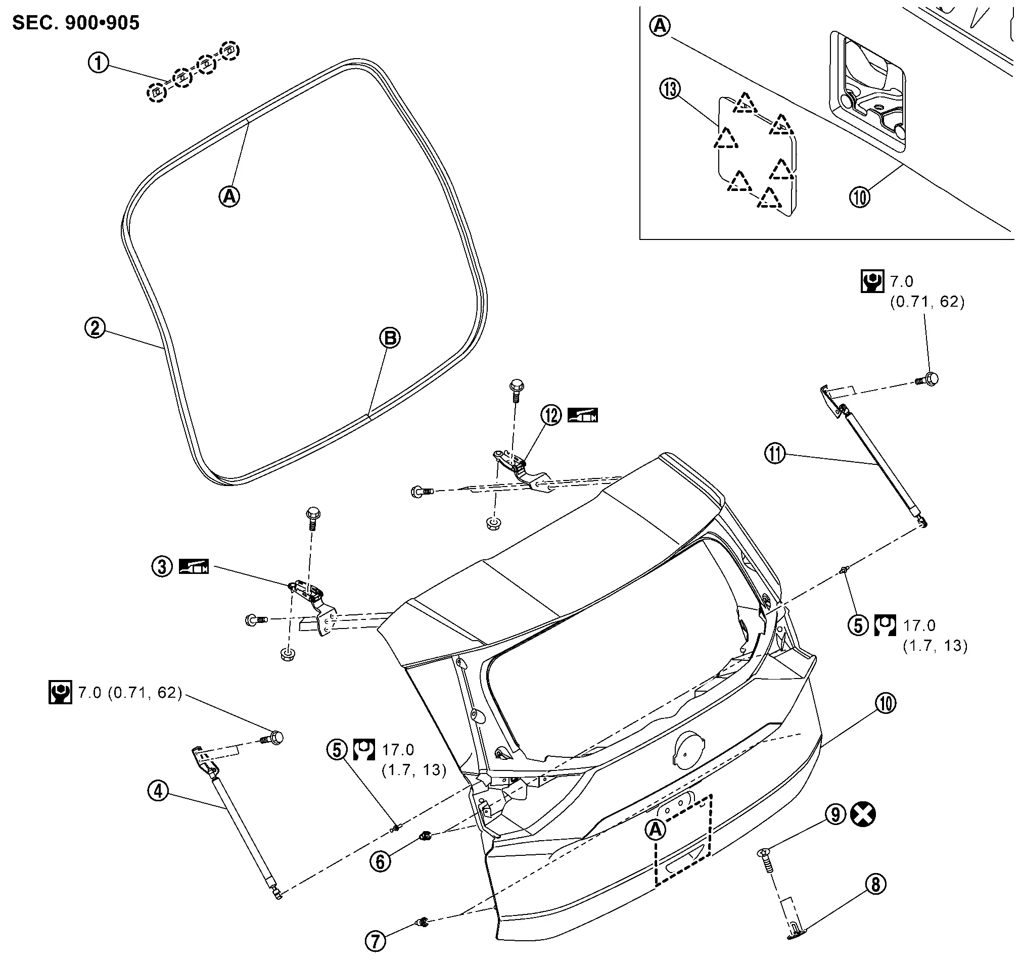
 |
Roof seal |  |
Back door weather-strip |  |
Back door hinge LH |
 |
Back door stay LH* |  |
Stud ball |  |
Back door bumper rubber upper |
 |
Back door bumper rubber lower |  |
Back door striker |  |
TORX bolt |
 |
Back door panel |  |
Back door stay RH* |  |
Back door hinge RH |
 |
Back door plate assembly | ||||
 |
: Center mark | ||||
 |
: Seam | ||||
| * | : Without automatic back door models | ||||
 |
: Clip | ||||
 |
: Pawl | ||||
 |
: Always replace after every disassembly. | ||||
 |
: N┬Ęm (kg-m, in-lb) | ||||
 |
: N┬Ęm (kg-m, ft-lb) | ||||
 |
: Body grease | ||||
Back Door Assembly
Removal and Installation
CAUTION:
-
Perform work with 2 workers, because it is heavy weight.
-
Support back door with a proper material and use protective tape or shop cloth to protect back door and body from falling and damage when removing and installing back door assembly.
REMOVAL
Remove luggage side upper finisher. Refer to Removal and Installation.
Remove rear side of headlining assembly, and then move headlining assembly to a location where it dose not inhibit work. Refer to Removal and Installation.
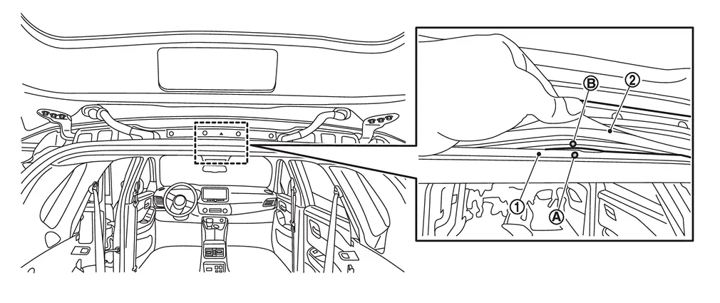
Disconnect harness connectors , and then disengage harness fixing clips.
|
: Clip |
| : Nissan Ariya Vehicle front |
Disconnect harness connector , and then disengage harness fixing clips.
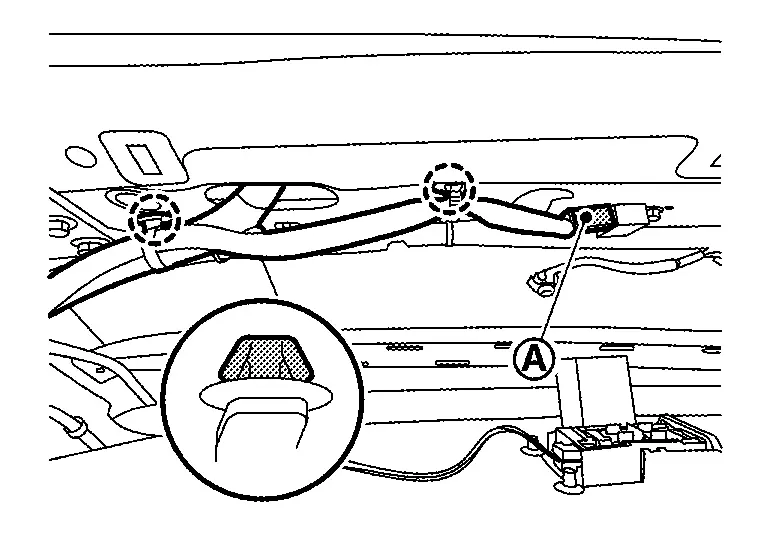
|
: Clip |
Remove grommet from roof panel, and then pull out back door harness from Nissan Ariya vehicle body.
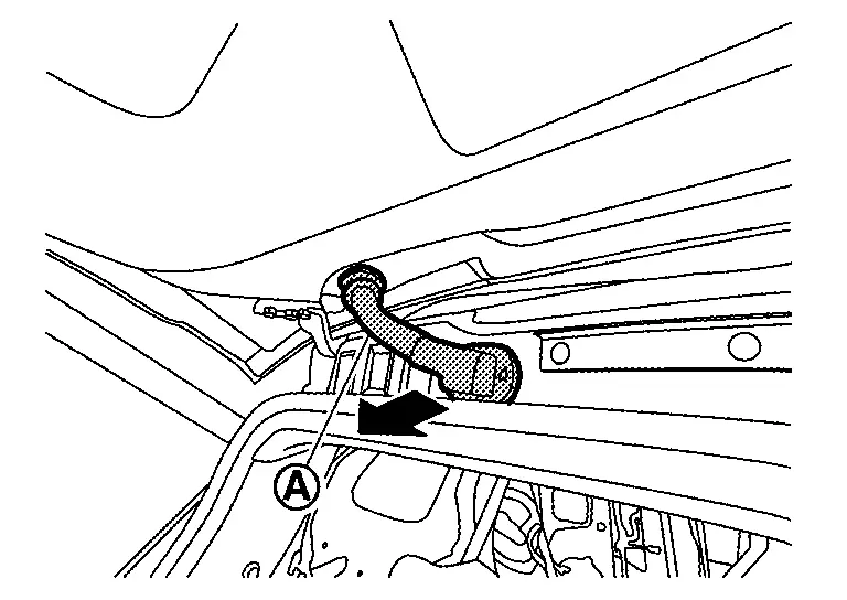
Disconnect rear washer tube B from joint. Refer to Removal and Installation.
Remove tube grommet from roof panel, and then pull out rear washer tube B from Nissan Ariya vehicle body.

Support back door assembly with the proper material to prevent it from falling.
WARNING:
Injury may occur if door assembly is not supported with a proper material when removing back door assembly.
Remove back door stay from stud ball (without automatic back door models). Refer to Removal and Installation.
CAUTION:
2 workers are required to support back door assembly.
Remove spindle unit from stud ball (with automatic back door models). Refer to Removal and Installation.
CAUTION:
2 workers are required to support back door assembly.
Remove back door hinge mounting bolts (back door panel side), and then remove back door assembly.
INSTALLATION
Note the following items, and then install in the reverse order of removal.
CAUTION:
-
Before installation, apply anticorrosive agent onto mounting surface.
-
After installation, perform the fitting adjustment. Refer to Adjustment.
-
After installation, check whether harness is not pinched. If harness is pinched, pull harness downward lightly.
-
After installation, check the open/close operation. Refer to Inspection.
-
Perform camera image calibration. Refer to Work Procedure (WITHOUT ProPILOT Assist 2.1) or Work Procedure (WITH ProPILOT Assist 2.1).
CAUTION:
Perform the calibration and perform the writing to the around view monitor control unit when removing and replacing each camera, removing the camera mounting parts (front grille, door mirror, etc.) and replacing the around view monitor control unit.
Inspection
Open and close the back door. Check that door hinge rotation portion moves smoothly.
Check back door hinge rotating part for poor lubrication. Apply body grease if necessary.
|
: Body grease |
Adjustment
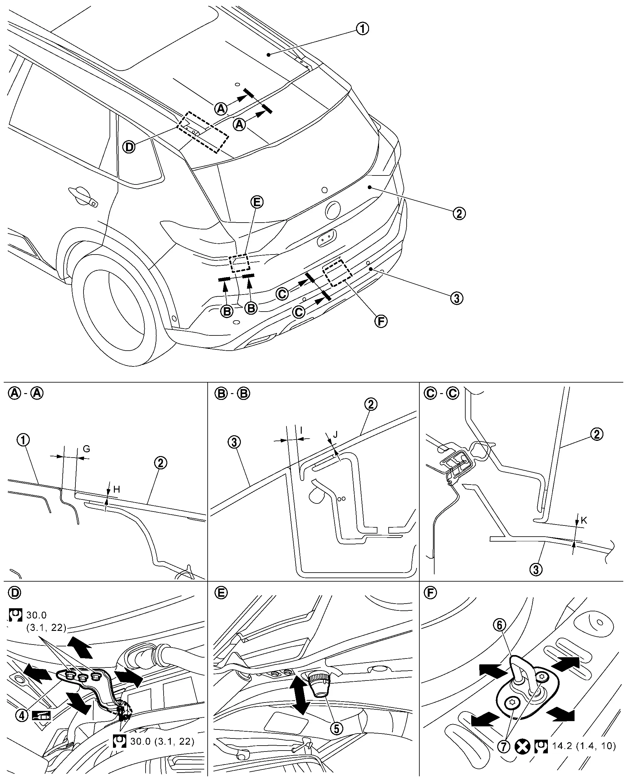
FITTING ADJUSTMENT
Fitting Adjustment Standard
|
Roof panel | |
Back door panel | |
Rear bumper fascia |
|
Back door hinge | |
Back door bumper rubber upper | |
Back door striker |
|
TORX bolt | ||||
|
: Always replace after every disassembly. | ||||
|
: N┬Ęm (kg-m, ft-lb) | ||||
|
: Body grease | ||||
Unit: mm [in]
| Portion | Standard |
Difference (LH/RH, MAX) | |||
|---|---|---|---|---|---|
| Roof panel ŌĆō Rear spoiler | ŌĆō |
G | Clearance |
5.4 ŌĆō 9.4 [0.213 ŌĆō 0.370] |
Ōē” 2.0 [0.079] |
| H | Surface height |
(ŌłÆ2.4) ŌĆō (+1.6) [(ŌłÆ0.094) ŌĆō (+0.063)] |
Ōē” 2.0 [0.079] |
||
| Back door panel ŌĆō Rear bumper fascia | ŌĆō |
I | Clearance |
2.5 ŌĆō 6.7 [0.098 ŌĆō 0.264] |
Ōē” 2.0 [0.079] |
| J | Surface height |
(ŌłÆ4.2) ŌĆō (0.0) [(ŌłÆ0.165) ŌĆō (0.000)] |
Ōē” 2.0 [0.079] |
||
 ŌĆō ŌĆō |
K | Clearance |
6.4 ŌĆō 10.8 [0.252 ŌĆō 0.425] |
ŌĆö | |
Check the clearance and the surface height between back door and each part by seeing and touching.
If the clearance and the surface height are out of specification, adjust them according to the procedures shown below.
Fitting Adjustment Procedure
Loosen back door hinge mounting bolts of back door side.
Remove luggage rear plate. Refer to Removal and Installation.
Remove back door striker. Refer to Removal and Installation.
Temporarily install back door striker.
CAUTION:
Do not loosen tightened bolts.
Position back door lock assembly and engage back door striker. Check back door lock assembly and back door striker for looseness.
Adjust the clearance and surface height of back door according to the fitting standard dimension by moving back door assembly and adjusting bumper rubber upper.
Tighten back door striker mounting TORX bolts, and back door hinge mounting bolts of back door side to the specified torque.
Install luggage rear plate. Refer to Removal and Installation.
CAUTION:
-
After adjusting, check that bumper rubber is in contact with Nissan Ariya vehicle body surely.
-
After adjusting, check the open/close operation. Refer to Inspection.
-
After adjusting, perform calibration of automatic back door position information. Refer to Work Procedure.
-
After adjusting, perform calibration camera image (with around view monitor). Refer to Work Procedure.
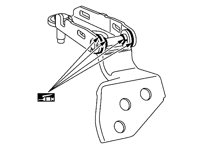
BACK DOOR STRIKER ADJUSTMENT
Adjust back door striker so that it becomes parallel with back door lock insertion direction.
Back Door Striker
Removal and Installation
REMOVAL
Remove luggage rear plate. Refer to Removal and Installation.
Remove mounting TORX bolts, and then remove back door striker.
INSTALLATION
Note the following items, and then install in the reverse order of removal.
CAUTION:
-
Never reuse TORX bolt. Always replace it with a new one when it is removed.
-
After installation, perform the fitting adjustment. Refer to Adjustment.
Back Door Hinge
Removal and Installation
REMOVAL
Remove back door assembly. Refer to Removal and Installation.
Remove headlining assembly. Refer to Removal and Installation.
Remove back door hinge mounting bolts and nut, and then remove back door hinge.
INSTALLATION
Note the following items, and then install in the reverse order of removal.
CAUTION:
-
Before installation, apply anticorrosive agent onto mounting surface.
-
After installation, perform the fitting adjustment. Refer to Adjustment.
-
After installation, check the open/close operation. Refer to Inspection.
Back Door Stay
Removal and Installation
REMOVAL
CAUTION:
2 workers are required to support back door.
Support the back door with the suitable material to prevent it from falling.
WARNING:
Bodily injury may occur if no supporting rod is holding the back door open when removing the back door stay.
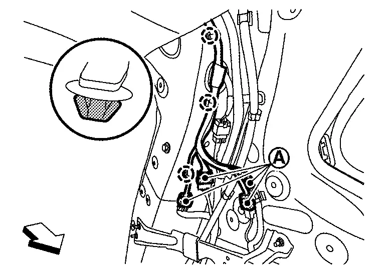
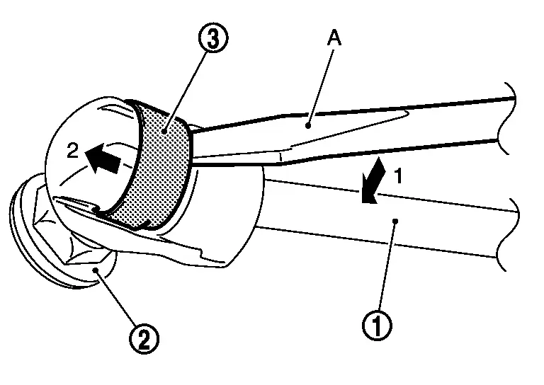
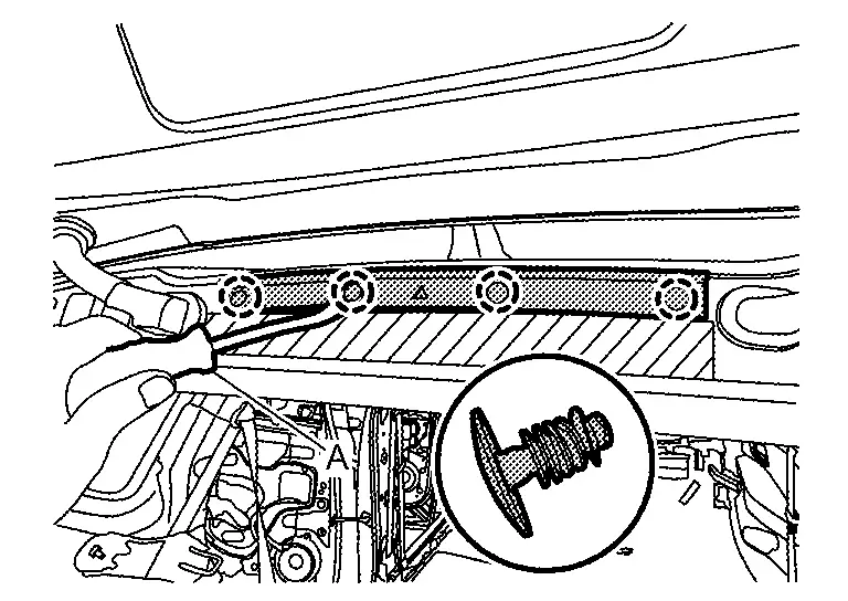
Remove metal clip located on connection between back door stay and stud ball using a remover tool (A) according to the numerical order 1ŌåÆ2 indicated by arrows as shown in the figure.
CAUTION:
2 workers are required to support back door.
Disengage back door stay and stud ball of back door side.
Remove back door stay mounting bolts, and then remove back door stay.
INSTALLATION
Installation is in the reverse order of removal.
Disposal
CAUTION:
When performing disposal operation, wear the protective glasses and protective gloves.
Fix back door stay using a vise (C).
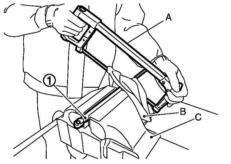
CAUTION:
When cutting a hole on back door stay, always cover a hacksaw (A) using a shop cloth (B) to avoid scattering metal fragments or oil.
Using hacksaw slowly make 2 holes in the back door stay, in numerical order as shown in the figure.
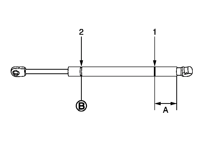
| A: | 20.0 mm (0.787 in) |
| : |
Cut at the groove. |
Back Door Weather-Strip
Removal and Installation
REMOVAL
Pull up and remove engagement with body from weather-strip joint.
CAUTION:
Never pull strongly on back door weather-strip.
INSTALLATION
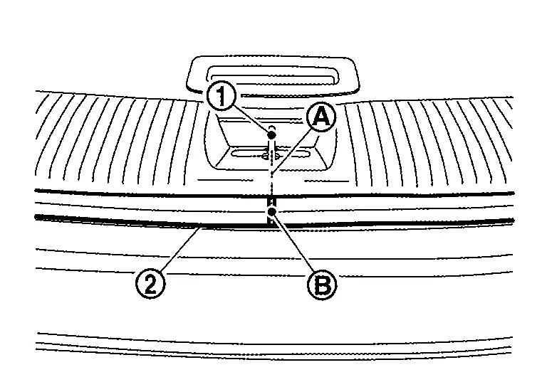
Working from the upper section, align back door weather-strip (2) center mark (B) with vehicle center position mark (A) and install weather-strip onto the Nissan Ariya vehicle (1).
Align the seam (B) of back door weather-strip (2) with the center (A) of back door striker (1), and then install weather-strip onto the Nissan Ariya vehicle.
Pull back door weather-strip gently to ensure that there is no loose section.
CAUTION:
Check that weather-strip fits tightly in each corner.
Roof Seal
Removal and Installation
REMOVAL
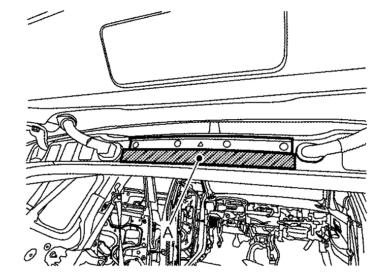
Apply protective tape (A) on the part to protect it from damage.
Disengage roof seal fixing clips using a removal tool (A), and then remove roof seal.
|
: Clip |
INSTALLATION
Installation is in the reverse order of removal.
Other materials:
P2123 App Sensor
DTC Description
DTC DETECTION LOGIC DTC
CONSULT screen terms
(Trouble diagnosis content)
DTC detection condition
P2123
00
APP SEN 1/CIRC
(Throttle/Pedal position sensor/switch D circuit high)
Diagnosis condition
Engine running at idle
Signal (terminal)
Accelerator ...
System Description. System. Warning/indicator/chime List
Warning/indicator/chime List
Warning Lamp/Indicator Lamp/Information display
Warning lamp Item Design Reference
Seat belt warning lamp
For layout, refer to Design.
For function, refer to Seat Belt Warning Lamp.
Information display Item Reference
Rear seat belt warning
Ref ...
Ecu Diagnosis Information. Ecm, Bcm, Intelligent Key Unit, Ipdm E/r
List of ECU Reference
ECU Reference
ECM
Values On The Diagnosis Tool
Values On The Diagnosis Tool
Physical Values
Physical Values
Fail-safe
Fail-safe
DTC Inspection Priority Chart
DTC Inspection Priority Chart
DTC Index
DTC Index
BCM
Reference Valu ...