Nissan Rogue Service Manual: Removal and installation
AWD CONTROL UNIT
Exploded View
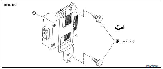
1 AWD control unit
 : Vehicle front
 : N┬Ęm (kg-m, in-lb)
Removal and Installation
REMOVAL
- Remove luggage side lower finisher (LH). Refer to INT-33, "Exploded View".
- Disconnect AWD control unit harness connector.
- Remove AWD control unit bolts (
 ).
).
NOTE: AWD control unit is located on the back side of body panel.
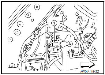
: Front
- Remove AWD control unit.
INSTALLATION
Installation is in the reverse order of removal.
CAUTION:
- Do not drop or shock AWD control unit.
- When replacing AWD control unit, perform writing unit characteristic. Refer to DLN-35, "Work Procedure".
AWD LOCK SWITCH
Exploded View
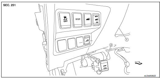
- Instrument lower panel LH
- AWD lock switch
Front
 Pawl
Pawl
Removal and Installation
REMOVAL
- Remove instrument lower panel LH. Refer to IP-22, "Removal and Installation".
- Disconnect AWD lock switch harness connector (A).
- Remove AWD lock switch from lower switch bracket (2).
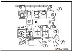
: Pawls
INSTALLATION
Install in the reverse order of removal.
TRANSFER COVER OIL SEAL
Removal and Installation
NOTE:
- Replacement on vehicle may cause damage to transfer cover, and may cause a transfer oil leak.
- If transfer cover oil seal requires replacement, remove the transfer assembly from the vehicle before replacing transfer cover oil seal. Refer to DLN-73, "Disassembly".
 Periodic maintenance
TRANSFER OIL
Inspection
TRANSFER OIL LEAKS
Check that transfer oil is not leaking from transfer assembly or around it.
TRANSFER OIL LEVEL
CAUTION:
Do not start engine while checking transfer oil ...
 Unit removal and installation
TRANSFER ASSEMBLY
Exploded View
1 Transfer assembly
: N┬Ęm (kg-m, ft-lb)
*: Apply anti-corrosion oil.
Removal and Installation
NOTE:
When removing components such as hoses, tubes/lines, etc ...
Other materials:
The low washer fluid warning continues displaying, or
does not display
Description
The warning is still displayed even after washer fluid is added.
The warning is not displayed even though the washer tank is empty.
Diagnosis Procedure
1.CHECK WASHER FLUID LEVEL SWITCH SIGNAL CIRCUIT
Check the washer fluid level switch signal circuit. Refer to MWI-71,
" ...
Basic inspection
DIAGNOSIS AND REPAIR WORK FLOW
Work Flow
DETAILED FLOW
1.OBTAIN INFORMATION ABOUT SYMPTOM
Interview the customer to obtain as much information as possible about the
conditions and environment under
which the malfunction occurs.
>> GO TO 2.
2.CHECK SYMPTOM
Check the symptom ...
Precaution
Precaution for Supplemental Restraint System (SRS) "AIR BAG" and "SEAT
BELT
PRE-TENSIONER"
The Supplemental Restraint System such as ŌĆ£AIR BAGŌĆØ and ŌĆ£SEAT BELT PRE-TENSIONERŌĆØ,
used along
with a front seat belt, helps to reduce the risk or severity of injury to the
...
