Nissan Rogue Service Manual: Removal and installation
GENERATOR
Exploded View
REMOVAL
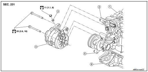
- Cylinder head
- Generator bracket
- Washer
- Generator
- Water pump
- Cylinder block
Removal and Installation
REMOVAL
- Disconnect negative terminal from battery. Refer to PG-75, "Exploded View".
- Remove wheel and tire (RH) using a power tool. Refer to WT-60, "Removal and Installation".
- Remove fender protector side cover. Refer to EXT-28, "FENDER PROTECTOR : Exploded View"
- Remove front air spoiler. Refer to EXT-16, "Exploded View".
- Remove engine under cover. Refer to EXT-37, "ENGINE UNDER COVER : Removal and Installation".
- Remove drive belt. Refer to EM-13, "Removal and Installation".
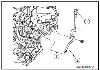
- Remove oil level gauge (1).
- Remove oil level gauge guide (2).
- Remove oil level gauge guide O-ring (3).
- Disconnect generator connector (A).
- Remove “B” terminal nut (B) and “B” terminal harness.
- Remove harness bracket (C).
NOTE: Harness ground does not have to be removed during bracket removal.
- Remove upper generator mounting bolt (D), using suitable tool.
- Remove lower generator mounting bolt (E), using suitable tool.
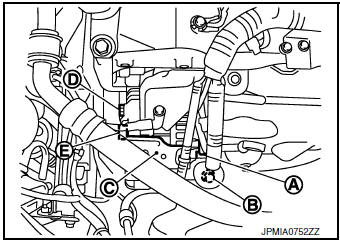
- Remove generator upward from the vehicle.
INSTALLATION
Installation is in the reverse order of removal.
- Tighten oil level gauge guide bolt to specification.
Oil level gauge guide bolt : 21.6 N·m (2.2 kg-m, 16 ft-lb)
CAUTION:
- Be careful to tighten “B” terminal nut carefully.
- Install generator and check tension of belt. Refer to EM-13, "Checking".
- Do not reuse oil level gauge guide O-ring.
- Prior to installation, apply clean engine oil to oil level gauge guide O-ring.
- Ensure O-ring sealing surface is free from dust or imprefections.
- Allow engine to run for 5 minutes and inspect for engine oil leaks.
Inspection
GENERATOR PULLEY INSPECTION
Perform the following.
- Make sure that the generator pulley does not bind or rattle.
- Make sure that the generator pulley is tight. Refer to CHG-20, "Exploded View".
 Symptom diagnosis
CHARGING SYSTEM
Symptom Table
...
 Service data and specifications (SDS)
Generator
...
Other materials:
Removal and installation
FRONT COMBINATION LAMP
Exploded View
Front fender
Front combination lamp
Clip
Removal and Installation
REMOVAL
Remove front bumper fascia. Refer to EXT-17, "Removal and
Installation".
Remove front combination lamp bolts and clip.
Pull front combinat ...
Engine compartment
CAUTIONNever use a fuse of a higher or lower
amperage rating than specified on the
fuse box cover. This could damage the
electrical system or cause a fire.
Two types of fuses are used. Type A is used in
the fuse boxes in the engine compartment. Type
B is used in the passe ...
System description
DESCRIPTION
Engine Cooling System
Thermostat
Water outlet
Cylinder block (Thermostat housing)
Water inlet
Radiator
Water pump
Cylinder block
Cylinder head
Open
Closed
To electric throttle control actuator
To oil cooler
...
