Nissan Rogue Service Manual: P0031, P0032 A/F sensor 1 heater
DTC Description
DTC DETECTION LOGIC
| DTC No. | CONSULT screen terms (Trouble diagnosis content) | DTC detecting condition |
| P0031 | A/F SEN1 HTR (B1) [Air fuel ratio (A/F) sensor 1 heater (bank 1)control circuit low] | The current amperage in the A/F sensor 1 heater circuit is out of
the normal
range.
(An excessively low voltage signal is sent to ECM through the A/F sensor 1 heater.) |
| P0032 | A/F SEN1 HTR (B1) [Air fuel ratio (A/F) sensor 1 heater (bank 1)control circuit high] | The current amperage in the A/F sensor 1 heater circuit is out of
the normal
range.
(An excessively high voltage signal is sent to ECM through the A/F sensor 1 heater.) |
POSSIBLE CAUSE
DTC P0031
- Harness or connectors (A/F sensor 1 heater circuit is open or shorted.)
- A/F sensor 1 heater
DTC P0032
- Harness or connectors (A/F sensor 1 heater circuit is shorted.)
- A/F sensor 1 heater
FAIL-SAFE
Not applicable
DTC CONFIRMATION PROCEDURE
1.PRECONDITIONING
If DTC Confirmation Procedure has been previously conducted, always perform the following procedure before conducting the next test.
- Turn ignition switch OFF and wait at least 10 seconds.
- Turn ignition switch ON.
- Turn ignition switch OFF and wait at least 10 seconds.
TESTING CONDITION: Before performing the following procedure, confirm that battery voltage is more than between 11 V at idle. >> GO TO 2.
2.PERFORM DTC CONFIRMATION PROCEDURE
- Start engine and let it idle for at least 10 seconds.
- Check 1st trip DTC.
Is 1st trip DTC detected? YES >> Proceed to EC-185, "Diagnosis Procedure".
NO >> INSPECTION END
Diagnosis Procedure
1.CHECK AIR FUEL RATIO (A/F) SENSOR 1 POWER SUPPLY CIRCUIT
- Disconnect air fuel ratio (A/F) sensor 1 harness connector.
- Turn ignition switch ON.
- Check the voltage between A/F sensor 1 harness connector and ground.
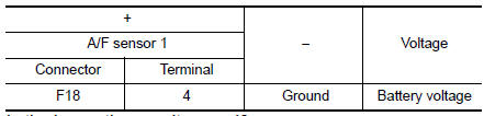
Is the inspection result normal? YES >> GO TO 2.
NO >> Repair or replace error-detected parts.
2.CHECK A/F SENSOR 1 HEATER OUTPUT SIGNAL CIRCUIT
- Turn ignition switch OFF.
- Disconnect ECM harness connector.
- Check the continuity between A/F sensor 1 harness connector and ECM harness connector.
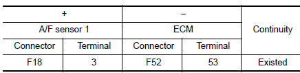
- Also check harness for short to ground and to power.
Is the inspection result normal? YES >> GO TO 3.
NO >> Repair open circuit, short to ground or short to power in harness or connectors.
3.CHECK A/F SENSOR 1 HEATER Check the A/F sensor 1 heater. Refer to EC-186, "Component Inspection".
Is the inspection result normal? YES >> GO TO 5.
NO >> GO TO 4.
4.REPLACE AIR FUEL RATIO (A/F) SENSOR 1
Replace malfunctioning air fuel ratio (A/F) sensor 1. Refer to EM-29, "Exploded View".
CAUTION:
- Discard any A/F sensor which has been dropped from a height of more than 0.5 m (19.7 in) onto a hard surface such as a concrete floor; use a new one.
- Before installing new A/F sensor, clean exhaust system threads using Oxygen Sensor Thread Cleaner [commercial service tool (J-43897-18 or J-43897-12)] and approved Anti-seize Lubricant (commercial service tool).
>> INSPECTION END
5.CHECK INTERMITTENT INCIDENT
Refer to GI-41, "Intermittent Incident".
>> INSPECTION END
Component Inspection
1.CHECK AIR FUEL RATIO (A/F) SENSOR 1
- Turn ignition switch OFF.
- Disconnect A/F sensor 1 harness connector.
- Check resistance between A/F sensor 1 terminals as per the following.
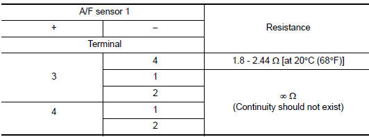
Is the inspection result normal? YES >> INSPECTION END
NO >> GO TO 2.
2.REPLACE AIR FUEL RATIO (A/F) SENSOR 1
Replace air fuel ratio (A/F) sensor 1. Refer to EM-29, "Exploded View".
CAUTION:
- Discard any sensor which has been dropped from a height of more than 0.5 m (19.7 in) onto a hard surface such as a concrete floor; use a new one.
- Before installing new sensor, clean exhaust system threads using Oxygen Sensor Thread Cleaner [commercial service tool (J-43897-18 or J43897-12)] and approved Anti-seize Lubricant (commercial service tool).
>> INSPECTION END
 P0014 EVT control
DTC Description
DTC DETECTION LOGIC
DTC No.
CONSULT screen terms
(Trouble diagnosis content)
DTC detecting condition
P0014
EXH/V TIM CONT-B1
(″B″ Camshaft ...
 P0037, P0038 HO2S2 heater
DTC Description
DTC DETECTION LOGIC
DTC No.
CONSULT screen terms
(Trouble diagnosis content)
DTC detecting condition
P0037
HO2S2 HTR (B1)
(HO2S heater control circuit ...
Other materials:
Reporting safety defects
For USA
If you believe that your vehicle has a defect
which could cause a crash or could
cause injury or death, you should immediately
inform the National Highway Traffic
Safety Administration (NHTSA) in addition
to notifying NISSAN.
If NHTSA receives similar complaints, it
may open an inv ...
Windows
POWER WINDOWS
WARNING
Make sure that all passengers have
their hands, etc. inside the vehicle while
it is in motion and before closing the
windows. Use the window lock switch to
prevent unexpected use of the power
windows.
Do not leave children unatten ...
Rear-facing child restraint installation using the seat belts
Rear-facing child restraint installation using the seat belts
WARNINGThe three-point seat belt with Automatic
Locking Retractor (ALR) must be used
when installing a child restraint. Failure to
use the ALR mode will result in the child
restraint not being properly secured. The ...
