Nissan Rogue Service Manual: P0014 EVT control
DTC Description
DTC DETECTION LOGIC
| DTC No. | CONSULT screen terms (Trouble diagnosis content) | DTC detecting condition |
| P0014 | EXH/V TIM CONT-B1 (″B″ Camshaft position - timing over-advanced or system performance bank 1) | There is a gap between angle of target and phase-control angle degree. |
POSSIBLE CAUSE
- Crankshaft position sensor (POS)
- Camshaft position sensor (PHASE)
- Exhaust valve timing control position sensor
- Exhaust valve control solenoid valve
- Accumulation of debris to the signal pick-up portion of the camshaft
- Timing chain installation
- Foreign matter caught in the oil groove for exhaust valve timing control
FAIL-SAFE
Device fix mode
DTC CONFIRMATION PROCEDURE
1.CHECK DTC PRIORITY
If DTC P0014 is displayed with DTC P0078 or P1078, first perform the trouble diagnosis for DTC P0078 or P1078.
Is applicable DTC detected? YES >> Perform diagnosis of applicable. Refer to EC-93, "DTC Index".
NO >> GO TO 2.
2.PRECONDITIONING
If DTC Confirmation Procedure has been previously conducted, always perform the following procedure before conducting the next test.
- Turn ignition switch OFF and wait at least 10 seconds.
- Turn ignition switch ON.
- Turn ignition switch OFF and wait at least 10 seconds.
TESTING CONDITION: Before performing the following procedure, confirm that battery voltage is between 10 V and 16 V at idle.
>> GO TO 3.
3.PERFORM DTC CONFIRMATION PROCEDURE-1
 With CONSULT
- Turn ignition switch ON and select “DATA MONITOR” mode of “ENGINE” using CONSULT.
- Start engine and warm it up to the normal operating temperature.
- Maintain the following conditions for at least 6 consecutive seconds. Hold the accelerator pedal as steady as possible.
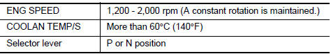
- Let engine idle for 10 seconds.
- Check 1st trip DTC.
 With GST
Follow the procedure “With CONSULT” above.
Is 1st trip DTC detected? YES >> Proceed to EC-182, "Diagnosis Procedure" NO >> GO TO 4.
4.PERFORM DTC CONFIRMATION PROCEDURE-2
With CONSULT
- Select “DATA MONITOR” mode of “ENGINE” using CONSULT.
- Maintain the following conditions for at least 20 consecutive seconds.
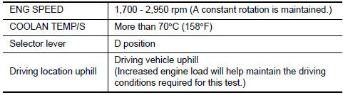
CAUTION: Always drive at a safe speed.
- Check 1st trip DTC.
With GST
Follow the procedure “With CONSULT” above.
Is 1st trip DTC detected? YES >> Proceed to EC-182, "Diagnosis Procedure" NO >> INSPECTION END
Diagnosis Procedure
1.CHECK DTC PRIORITY
If DTC P0014 is displayed with DTC P0078 or P1078, first perform the trouble diagnosis for DTC P0078 or P1078.
Is applicable DTC detected? YES >> Perform diagnosis of applicable. Refer to EC-93, "DTC Index".
NO >> GO TO 2.
2.CHECK OIL PRESSURE WARNING LAMP
- Start engine.
- Check oil pressure warning lamp and confirm it is not illuminated.
Is oil pressure warning lamp illuminated? YES >> Check the engine oil level. Refer to LU-7, "Inspection".
NO >> GO TO 3.
3.CHECK EXHAUST VALVE TIMING CONTROL SOLENOID VALVE
Check the exhaust valve timing control solenoid valve. Refer to EC-179, "Component Inspection".
Is the inspection result normal? YES >> GO TO 4.
NO >> Replace exhaust valve timing control solenoid valve. Refer to EM-44, "Exploded View".
4.CHECK CRANKSHAFT POSITION SENSOR (POS)
Check the crankshaft position sensor (POS). Refer to EC-297, "Component Inspection (Crankshaft Position sensor)".
Is the inspection result normal? YES >> GO TO 5.
NO >> Replace crankshaft position sensor (POS). Refer to EM-92, "Exploded View".
5.CHECK EXHAUST VALVE TIMING CONTROL POSITION SENSOR
Check the exhaust valve timing control position sensor. Refer to EC-387, "Component Inspection".
Is the inspection result normal? YES >> GO TO 6.
NO >> Replace exhaust valve timing control position sensor. Refer to EM-44, "Exploded View".
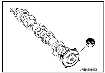
6.CHECK CAMSHAFT (EXH)
Check the following.
- Accumulation of debris to the signal plate of camshaft rear end
- Chipping signal plate of camshaft rear end
Is the inspection result normal? YES >> GO TO 7.
NO >> Remove debris and clean the signal plate of camshaft rear end or replace camshaft. Refer to EM-64, "Removal and Installation".
7.CHECK TIMING CHAIN INSTALLATION
Check service records for any recent repairs that may cause timing chain misaligned.
Are there any service records that may cause timing chain misaligned? YES >> Check timing chain installation. Refer to EM-45, "Removal and Installation".
NO >> GO TO 8.
8.CHECK LUBRICATION CIRCUIT
Refer to LU-7, "Inspection".
Is the inspection result normal? YES >> GO TO 9.
NO >> Clean lubrication line.
9.CHECK INTERMITTENT INCIDENT
Refer to GI-41, "Intermittent Incident".
>> INSPECTION END
Component Ins
1.CHECK EXHAUST VALVE TIMING CONTROL SOLENOID VALVE-1
- Turn ignition switch OFF.
- Disconnect exhaust valve timing control solenoid valve harness connector.
- Check resistance between exhaust valve timing control solenoid valve terminals as per the following.
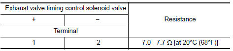
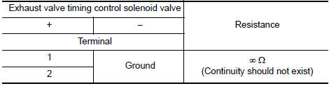
Is the inspection result normal? YES >> GO TO 2.
NO >> Replace exhaust valve timing control solenoid valve. Refer to EM-44, "Exploded View".
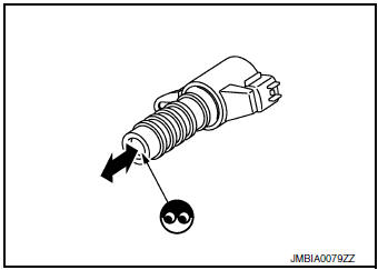
2.CHECK EXHAUST VALVE TIMING CONTROL SOLENOID VALVE-2
- Remove exhaust valve timing control solenoid valve. Refer to EM-44, "Exploded View".
- Provide 12 V DC between exhaust valve timing control solenoid valve terminals 1 and 2, and then interrupt it. Check that the plunger moves as shown in the figure.
CAUTION: Do not apply 12 V DC continuously for 5 seconds or more.
Doing so may result in damage to the coil in exhaust valve timing control solenoid valve.
NOTE: Always replace O-ring when exhaust valve timing control solenoid valve is removed.
Is the inspection result normal? YES >> INSPECTION END
NO >> Replace exhaust valve timing control solenoid valve. Refer to EM-44, "Exploded View"
 P0011 IVT control
DTC Description
DTC DETECTION LOGIC
DTC No.
CONSULT screen terms
(Trouble diagnosis content)
DTC detecting condition
P0011
INT/V TIM CONT-B1
(″A″ Camshaft ...
 P0031, P0032 A/F sensor 1 heater
DTC Description
DTC DETECTION LOGIC
DTC No.
CONSULT screen terms
(Trouble diagnosis content)
DTC detecting condition
P0031
A/F SEN1 HTR (B1)
[Air fuel ratio (A/F) sens ...
Other materials:
General maintenance
During the normal day-to-day operation of the
vehicle, general maintenance should be performed
regularly as prescribed in this section. If
you detect any unusual sounds, vibrations or
smells, be sure to check for the cause or have a
NISSAN dealer do it promptly. In addition, you
should notify ...
NISSAN Vehicle Immobilizer System keys
You can only drive your vehicle using the master
keys which are registered to the NISSAN Vehicle
Immobilizer System components in your vehicle.
These keys have a transponder chip in the key
head.
The master key can be used for all the locks.
Never leave these keys in the vehicle.
Additi ...
Symptom diagnosis
SQUEAK AND RATTLE TROUBLE DIAGNOSES
Work Flow
CUSTOMER INTERVIEW
Interview the customer if possible, to determine the conditions that exist
when the noise occurs. Use the Diagnostic
Worksheet during the interview to document the facts and conditions when the
noise occurs and any
custome ...
