Nissan Rogue Service Manual: P1805 brake switch
DTC Description
DTC DETECTION LOGIC
| DTC No. | CONSULT screen terms (Trouble diagnosis content) | DTC detecting condition |
| P1805 | BRAKE SW/CIRCUIT (BRAKE SW/CIRCUT) | A stop lamp switch signal is not sent to ECM for extremely long time while the vehicle is driving. |
POSSIBLE CAUSE
- Harness or connectors (Stop lamp switch circuit is open or shorted.)
- Stop lamp switch
FAIL-SAFE ECM controls the electric throttle control actuator by regulating the throttle opening to a small range. Therefore, acceleration will be poor.
| Vehicle condition | Driving condition |
| When engine is idling | Normal |
| When accelerating | Poor acceleration |
DTC CONFIRMATION PROCEDURE
1.PERFORM DTC CONFIRMATION PROCEDURE
- Turn ignition switch ON.
- Fully depress the brake pedal for at least 5 seconds.
- Erase the DTC.
- Check 1st trip DTC.
Is 1st trip DTC detected? YES >> Proceed to EC-418, "Diagnosis Procedure".
NO >> INSPECTION END
Diagnosis Procedure
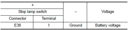
1.CHECK STOP LAMP SWITCH POWER SUPPLY CIRCUIT
- Turn ignition switch OFF.
- Disconnect stop lamp switch harness connector.
- Check the voltage between stop lamp switch harness connector and ground.
Is the inspection result normal? YES >> GO TO 2.
NO >> Perform the trouble diagnosis for power supply circuit.
2.CHECK STOP LAMP SWITCH GROUND CIRCUIT
- Disconnect ECM harness connector.
- Check the continuity between stop lamp switch harness connector and ECM harness connector
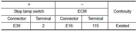
- Also check harness for short to ground and to power.
Is the inspection result normal? YES >> GO TO 3.
NO >> Repair or replace error-detected parts.
3.CHECK STOP LAMP SWITCH
Check the stop lamp switch. Refer to EC-412, "Component Inspection (Stop Lamp Switch)".
Is the inspection result normal? YES >> Check intermittent incident. Refer to GI-41, "Intermittent Incident".
NO >> Replace stop lamp switch. Refer to BR-20, "Exploded View".
Component Inspection (Stop Lamp Switch)
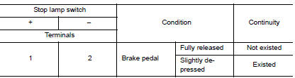
1.CHECK STOP LAMP SWITCH-1
- Turn ignition switch OFF.
- Disconnect stop lamp switch harness connector.
- Check the continuity between stop lamp switch terminals as per the following conditions.
Is the inspection result normal? YES >> INSPECTION END
NO >> GO TO 2.
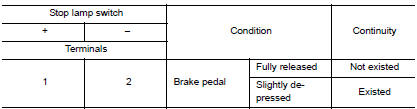
2.CHECK STOP LAMP SWITCH-2
- Adjust stop lamp switch installation. Refer to BR-15, "Adjustment".
- Check the continuity between stop lamp switch terminals as per the following conditions.
Is the inspection result normal? YES >> INSPECTION END
NO >> Replace stop lamp switch. Refer to BR-20, "Exploded View".
 P1715 input speed sensor
Description
ECM receives input speed sensor signal from TCM through CAN communication
line. ECM uses this signal for
engine control.
DTC Description
DTC DETECTION LOGIC
DTC No.
CONSUL ...
 P2004 intake manifold runner control valve
DTC Description
DTC DETECTION LOGIC
DTC No.
CONSULT screen terms
(Trouble diagnosis content)
DTC detecting condition
P2004
TUMBLE CONT/V
(Intake manifold runner contro ...
Other materials:
Periodic maintenance
REAR PROPELLER SHAFT
Inspection
APPEARANCE AND NOISE
Check the propeller shaft tube surface for dents or cracks. If
malfunction is detected, replace propeller shaft
assembly.
If center bearing is noisy or damaged, replace propeller shaft
assembly.
VIBRATION
If vibrati ...
C119A vacuum sensor
DTC Logic
DTC DETECTION LOGIC
DTC
Display Item
Malfunction detected condition
Possible causes
C119A
VACUUM SEN VOLT
When a malfunction is detected in supply power voltage
of vacuum sensor.
Harness or connector
Vacuum sensor (brake booster)
...
Liftgate
WARNING
Always be sure the liftgate has been
closed securely to prevent it from opening
while driving.
Do not drive with the liftgate open. This
could allow dangerous exhaust gases
to be drawn into the vehicle. Refer to
“Exhaust gas (carbon monoxide)â ...
