Nissan Rogue Service Manual: C119A vacuum sensor
DTC Logic
DTC DETECTION LOGIC
| DTC | Display Item | Malfunction detected condition | Possible causes |
| C119A | VACUUM SEN VOLT | When a malfunction is detected in supply power voltage of vacuum sensor. |
|
DTC CONFIRMATION PROCEDURE
1.CHECK SELF-DIAGNOSTIC RESULT
 With CONSULT.
- Turn the ignition switch ON.
- Perform self-diagnostic result.
Is DTC C119A detected? YES >> Proceed to diagnosis procedure. Refer to BRC-111, "Diagnosis Procedure".
NO >> Inspection End.
Diagnosis Procedure
Regarding Wiring Diagram information, refer to BRC-57, "Wiring Diagram".
1.CHECK VACUUM SENSOR POWER SUPPLY
- Turn the ignition switch OFF.
- Disconnect vacuum sensor harness connector.
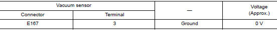
- Check voltage between vacuum sensor harness connector and ground.
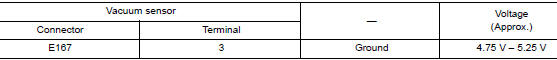
- Turn the ignition switch ON.
CAUTION: Never start engine.
- Check voltage between vacuum sensor harness connector and ground.
Is the inspection result normal? YES >> GO TO 3.
NO >> GO TO 2.
2.CHECK VACUUM SENSOR POWER SUPPLY CIRCUIT
- Turn the ignition switch OFF.
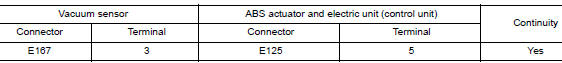
- Disconnect ABS actuator and electric unit (control unit) harness connector.
- Check continuity between vacuum sensor harness connector and ABS actuator and electric unit (control unit) harness connector.
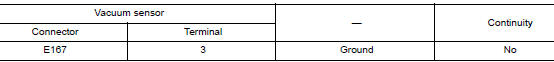
- Check continuity between vacuum sensor harness connector and ground.
Is the inspection result normal? YES >> Perform diagnosis of ABS actuator and electric unit (control unit) power supply and ground circuit.
Refer to BRC-111, "Diagnosis Procedure".
NO >> Repair or replace malfunctioning components.
3.CHECK VACUUM SENSOR GROUND CIRCUIT
- Turn the ignition switch OFF.
- Check continuity between vacuum sensor harness connector and ground.
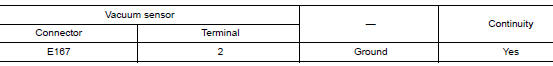
Is the inspection result normal? YES >> GO TO 4.
NO >> Repair or replace malfunctioning components.
4.CHECK TERMINAL
- Check vacuum sensor pin terminals for damage or loose connection with harness connector.
- Check ABS actuator and electric unit (control unit) pin terminals for damage or loose connection with harness connector.
Is the inspection result normal? YES >> Replace ABS actuator and electric unit (control unit). Refer to BRC-136, "Removal and Installation".
NO >> Repair or replace malfunctioning components.
 C1199 brake booster
DTC Logic
DTC DETECTION LOGIC
DTC
Display Item
Malfunction detected condition
Possible causes
C1199
BRAKE BOOSTER
When brake booster vacuum is approx. 0 kPa (0 mm-
...
 U1000 CAN COMM CIRCUIT
Description
CAN communication allows a high rate of information transmission through the
two communication lines
(CAN-H line and CAN-L line) connecting various control units in the system. Each
...
Other materials:
Parking brake shoe
Exploded View
Back plate
Parking brake shoe
Brake strut
Return spring
Spring
Return spring to brake strut
Adjuster
Toggle lever
Anti-rattle pin
: Apply PBC (Poly Butyl
Cuprysil) grease or silicone-based grease
Removal and Installation
REMOVAL
WARNING ...
B1429 seat belt buckle switch RH
Description
DTC B1429 SEAT BELT BUCKLE SWITCH RH
The air bag diagnosis sensor unit monitors the seat belt buckle switch RH
status. If the control unit detects an
open or short condition in the circuit, it will set the DTC.
PART LOCATION
Refer to SRC-6, "Component Parts Location".
D ...
Wiring diagram
NAVIGATION WITHOUT BOSE
Wiring Diagram
...
