Nissan Rogue (T33) 2021-Present Service Manual: P052a Intake Valve Timing Control
DTC Description
DTC DETECTION LOGIC
| DTC |
CONSULT screen terms (Trouble diagnosis content) | DTC detection condition | ||
|---|---|---|---|---|
| P052A | 00 |
CAMSHAFT POSITION TIMING B1 (Cold start “A” camshaft position timing over-advanced bank 1) |
Diagnosis condition | Cold condition |
| Signal (terminal) | — | |||
| Threshold | There is a gap between angle of target and phase-control angle degree when the engine is in a cold condition. | |||
| Diagnosis delay time | — | |||
POSSIBLE CAUSE A
-
Intake valve timing control actuator
-
Intake valve timing control motor
-
Camshaft sprocket (INT)
-
Wear or damage of the electric intake valve timing control actuator brush
-
Center target
POSSIBLE CAUSE B
-
Accumulation of debris to the signal plate of the camshaft
-
Timing chain installation
FAIL-SAFE
Engine Control System
| Fail safe mode | Nissan Ariya Vehicle behavior | |
|---|---|---|
| Device fix mode |
|
|
Stop/Start System
When a DTC is detected, the stop/start indicator lamp blinks slowly and the stop/start system operation is prohibited. When ECM detects error while operating the stop/start system, ECM restarts the engine.
DTC Confirmation Procedure
PRECONDITIONING
TESTING CONDITION:
Before performing the following procedure, confirm that battery voltage is 10 V or more at idle.
 With CONSULT
-
Turn ignition switch OFF and wait at least 10 seconds.
-
Turn ignition switch ON.
-
Turn ignition switch OFF and wait at least 10 seconds.
-
Turn ignition switch ON.
-
On the CONSULT screen, select “ENGINE” >> “DATA MONITOR” >> “COOLANT TEMP/S”.
-
Check “COOLANT TEMP/S” indication value.
 With GST
Follow the procedure “With CONSULT” above.
Is the value of “COOLANT TEMP/S”−5°C (23°F) and 45°C (113°F)?
YES>>GO TO 2.
NO-1 [if it is below −5°C (23°F)]>>Warm up the engine until the value of “COOLANT TEMP/S” indicates −5°C (23°F) and 45°C (113°F). And then GO TO 2.
NO-2 [if it is above 45°C (113°F)]>>Cool the engine down to the value of “COOLANT TEMP/S” indicates −5°C (23°F) and 45°C (113°F). And then GO TO 2.
PERFORM DTC CONFIRMATION PROCEDURE
-
Turn ignition switch OFF and wait at 10 seconds.
-
Turn ignition switch ON.
-
Set the selector lever in N range.
-
Start the engine and let it idle for 20 seconds or more.
-
Check 1st trip DTC.
Is 1st trip DTC detected?
YES>>Proceed to DTC Diagnosis Procedure.
NO-1>>To check malfunction symptom before repair: Refer to Intermittent Incident.
NO-2>>Confirmation after repair: INSPECTION END
DTC Diagnosis Procedure
MALFUNCTION A
CAUTION:
Never reuse O-ring of electric intake valve timing control actuator. When replacing the electric intake valve timing control actuator, replace the O-ring.
CHECK ELECTRIC INTAKE VALVE TIMING CONTROL MOTOR CONTROL CIRCUIT
-
Turn ignition switch OFF.
-
Disconnect electric intake valve timing control motor harness connector.
-
Disconnect electric intake valve timing control module harness connector.
-
Check the continuity between the electric intake valve timing control motor harness connector and the electric intake valve timing control module harness connector.
Electric intake valve timing control motor Electric intake valve timing control module Continuity Connector Terminal Connector Terminal F91 1 F113 46 Existed 2 42 -
Also check harness for short to ground and short to power.
Is the inspection result normal?
YES>>GO TO 2.
NO>>Repair or replace error-detected parts.
CHECK ELECTRIC INTAKE VALVE TIMING CONTROL ACTUATOR BRUSH
-
Remove electric intake valve timing control actuator. Refer to Exploded View.
-
Check the state of brush for the electric intake valve timing control actuator.
Is the inspection result normal?
YES>>GO TO 3.
NO>>Replace the electric intake valve timing control actuator. Refer to Exploded View.
CHECK ELECTRIC INTAKE VALVE TIMING CONTROL ACTUATOR
-
Check the continuity between electric intake valve timing control actuator connector terminal and brush as following.
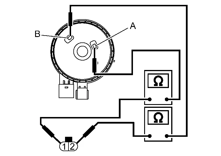
Electric intake valve timing control actuator Continuity Terminal Brush 1 A Existed B Not existed 2 B Existed A Not existed
Is the inspection result normal?
YES>>GO TO 4.
NO>>Replace the electric intake valve timing control actuator. Refer to Exploded View.
CHECK CENTER TARGET
Check the state of center target .
.
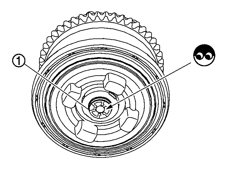
Is the inspection result normal?
YES>>Replace camshaft sprocket (INT) (Electric intake valve timing motor is built-in). Refer to Exploded View.
NO>>Repair or replace the center target. Refer to Exploded View.
MALFUNCTION B
CHECK TIMING CHAIN INSTALLATION
Check service records for any recent repairs that may cause timing chain misalignment.
Are there any service records that may cause timing chain misalignment?
YES>>Check timing chain installation. Refer to Removal and Installation.
NO>>GO TO 2.
CHECK CAMSHAFT SPROCKET AND TIMING CHAIN
Check the following.
-
Visually check for chipping camshaft
 sprocket gear tooth.
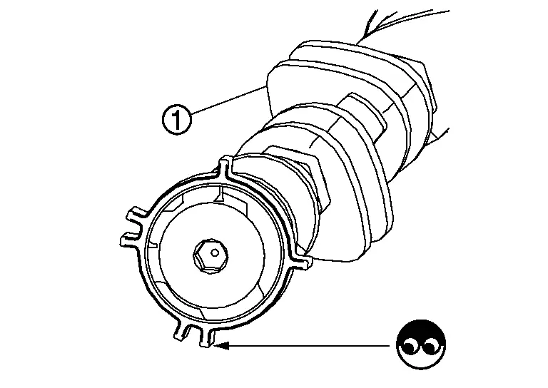
-
Timing chain tension and elongation.
Is the inspection result normal?
YES>>INSPECTION END
NO>>Repair or replace error-detected parts.
Other materials:
Transaxle Assembly
Exploded View
O-ring
Tube A
Control valve
O-ring
Oil strainer
Oil pan gasket
Oil pan
Drain plug gasket
Drain plug
Magnet
O-ring
O-ring
Tube B
Lip seal
Transaxle assembly
: Always replace after every disassembly ...
Turning the AEB with Pedestrian Detection system ON/OFF
AEB system OFF warning light (on the meter panel)
Vehicle information display
Steering-wheel-mounted controls (left side)
Follow the steps below to switch the AEB with Pedestrian Detection system on or off in your Nissan Rogue.
1. Press the
button until “Settings” appears in the vehicle ...
Symptom Diagnosis. Door Does Not Lock/unlock with Door Request Switch and Intelligent Key
Description
All doors do not lock/unlock using door request switch.SYMPTOM TABLE (BOTH INTELLIGENT KEYS HAVE THE SAME SYMPTOMS) Door lock operation (remote keyless entry)
Door lock operation (request switch of front/rear/back door) or
trunk/back door open operation (opener switch of trunk/back ...