Nissan Rogue Service Manual: P0447 EVAP canister vent control valve
DTC Description
DTC DETECTION LOGIC
| DTC No. | CONSULT screen terms (Trouble diagnosis content) | DTC detecting condition |
| P0447 | VENT CONTROL VALVE (Evaporative emission system vent control circuit open) | An improper voltage signal is sent to ECM through EVAP canister vent control valve. |
POSSIBLE CAUSE
- Harness or connectors (EVAP canister vent control valve circuit is open or shorted.)
- EVAP canister vent control valve
FAIL-SAFE
Not applicable
DTC CONFIRMATION PROCEDURE
1.PRECONDITIONING
If DTC Confirmation Procedure has been previously conducted, always perform the following procedure before conducting the next test.
- Turn ignition switch OFF and wait at least 10 seconds.
- Turn ignition switch ON.
- Turn ignition switch OFF and wait at least 10 seconds.
TESTING CONDITION: Before performing the following procedure, confirm battery voltage is more than 11 V at idle.
>> GO TO 2.
2.PERFORM DTC CONFIRMATION PROCEDURE
- Start engine and wait at least 8 seconds.
- Check 1st trip DTC.
Is 1st trip DTC detected? YES >> Proceed to EC-319, "Diagnosis Procedure".
NO >> INSPECTION END
Diagnosis Procedure
1.INSPECTION START
Do you have CONSULT? Do you have CONSULT? YES >> GO TO 2.
NO >> GO TO 3.
2.CHECK EVAP CANISTER VENT CONTROL VALVE CIRCUIT
 With CONSULT
- Turn ignition switch OFF and then turn ON.
- Select “VENT CONTROL/V” in “ACTIVE TEST” mode of “ENGINE” using CONSULT.
- Touch “ON/OFF” on CONSULT screen.
- Check for operating sound of the valve.
Clicking sound should be heard.
Is the inspection result normal? YES >> GO TO 7.
NO >> GO TO 3.
3.CHECK EVAP CANISTER VENT CONTROL VALVE POWER SUPPLY
- Turn ignition switch OFF.
- Disconnect EVAP canister vent control valve harness connector
- Turn ignition switch ON.
- Check the voltage between EVAP canister vent control valve harness connector and ground.
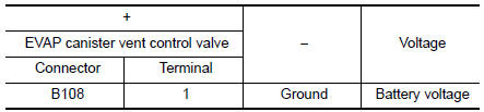
Is the inspection result normal? YES >> GO TO 5.
NO >> GO TO 4.
4.CHECK EVAP CANISTER VENT CONTROL VALVE POWER SUPPLY CIRCUIT
- Turn ignition switch OFF.
- Disconnect IPDM E/R harness connector.
- Check the continuity between EVAP canister vent control valve harness connector and IPDM E/R harness connector.
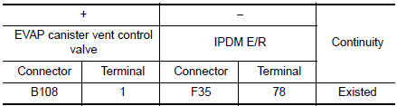
- Also check harness for short to ground.
Is the inspection result normal? YES >> Perform the trouble diagnosis for power supply circuit.
NO >> Repair or replace error-detected parts.
5.CHECK EVAP CANISTER VENT CONTROL VALVE OUTPUT SIGNAL CIRCUIT
- Turn ignition switch OFF.
- Disconnect ECM harness connector.
- Check the continuity between EVAP canister vent control valve harness connector and ECM harness connector.
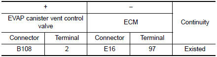
- Also check harness for short to power.
Is the inspection result normal? YES >> GO TO 6.
NO >> Repair or replace error-detected parts.
6.CHECK RUBBER TUBE FOR CLOGGING
- Disconnect rubber tube connected to EVAP canister vent control valve.
- Check the rubber tube for clogging.
Is the inspection result normal? YES >> GO TO 7.
NO >> Clean the rubber tube using an air blower.
7.CHECK EVAP CANISTER VENT CONTROL VALVE
Check the EVAP canister vent control valve. Refer to EC-321, "Component Inspection".
Is the inspection result normal? YES >> GO TO 8.
NO >> Replace EVAP canister vent control valve. Refer to FL-21, "Removal and Installation"
8.CHECK INTERMITTENT INCIDENT
Refer to GI-41, "Intermittent Incident".
>> INSPECTION END
Component Inspection
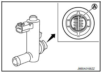
1.CHECK EVAP CANISTER VENT CONTROL VALVE-1
- Turn ignition switch OFF.
- Remove EVAP canister vent control valve from EVAP canister.
- Check portion A of EVAP canister vent control valve for being rusted.
Is it rusted? YES >> Replace EVAP canister vent control valve. Refer to FL- 21, "Removal and Installation".
NO >> GO TO 2.
2.CHECK EVAP CANISTER VENT CONTROL VALVE-2
 With CONSULT
- Reconnect harness connectors disconnected.
- Turn ignition switch ON.
- Perform “VENT CONTROL/V” in “ACTIVE TEST” mode of “ENGINE” using CONSULT.
- Check air passage continuity and operation delay time.
Make sure new O-ring is installed properly.
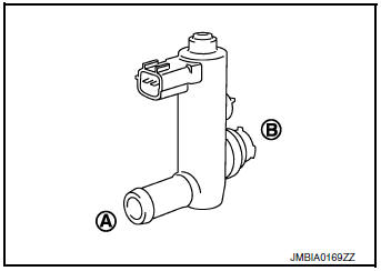
| Condition (VENT CONT/V) | Air passage continuity between A and B |
| ON | Not existed |
| OFF | Existed |
Operation takes less than 1 second.
 Without CONSULT
Check air passage continuity and operation delay time under the following conditions.
Make sure new O-ring is installed properly.
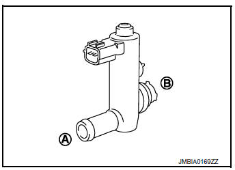
| Condition | Air passage continuity between A and B |
| 12 V direct current supply between terminals 1 and 2 | Not existed |
| OFF | Existed |
Operation takes less than 1 second.
Is the inspection result normal? YES >> GO TO 3.
NO >> Replace EVAP canister vent control valve. Refer to FL-21, "Removal and Installation".
3.CHECK EVAP CANISTER VENT CONTROL VALVE-3
With CONSULT
- Clean the air passage [portion to ] A of B EVAP canister vent control valve using an air blower.
- Perform “VENT CONTROL/V” in “ACTIVE TEST” mode of “ENGINE” using CONSULT.
- Check air passage continuity and operation delay time.
Make sure new O-ring is installed properly.

| Condition (VENT CONT/V) | Air passage continuity between A and B |
| ON | Not existed |
| OFF | Existed |
Operation takes less than 1 second.
Without CONSULT
- Clean the air passage [portion A to B] of EVAP canister vent control valve using an air blower.
- Check air passage continuity and operation delay time under the following conditions.
Make sure new O-ring is installed properly.
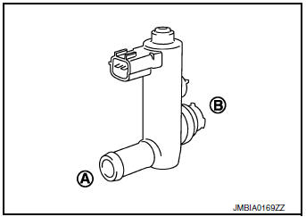
| Condition | Air passage continuity between A and B |
| 12 V direct current supply between terminals 1 and 2 | Not existed |
| OFF | Existed |
Operation takes less than 1 second.
Is the inspection result normal? YES >> INSPECTION END
NO >> Replace EVAP canister vent control valve. Refer to FL-21, "Removal and Installation".
 P0444, P0445 EVAP canister purge volume control solenoid
DTC Description
DTC DETECTION LOGIC
DTC No.
CONSULT screen terms
(Trouble diagnosis content)
DTC detecting condition
P0444
PURG VOLUME CONT/V
(Evaporative emission sys ...
 P0448 EVAP canister vent control valve
DTC Description
DTC DETECTION LOGIC
DTC No.
CONSULT screen terms
(Trouble diagnosis content)
DTC detecting condition
P0448
VENT CONTROL VALVE
(Evaporative emission sys ...
Other materials:
Unit disassembly and assembly
REAR DRIVE SHAFT
Exploded View
DISASSEMBLY
Circular clip
Dust shield
Slide joint housing
Snap ring
Spider assembly
Boot band
Boot
Shaft
Circular clip
Joint sub-assembly
Sensor rotor
: Wheel side
Disassembly and Assembly
DISASSEMBLY
Final Dri ...
P0452 EVAP control system pressure sensor
DTC Description
DTC DETECTION LOGIC
DTC No.
CONSULT screen terms
(Trouble diagnosis content)
DTC detecting condition
P0452
EVAP SYS PRES SEN
(Evaporative emission system pressure
sensor/switch low)
An excessively low voltage from the sensor is sent to ECM.
...
System description
SYSTEM
System Description
SYSTEM DIAGRAM
SYSTEM DESCRIPTION
The BCM has a CAN gateway function.
The BCM communicates between two CAN communication circuits.
The BCM selects and transmits only necessary information.
DIAGNOSIS SYSTEM (CAN GATEWAY)
CONSULT Function
...
