Nissan Rogue (T33) 2021-Present Service Manual: P014c A/f Sensor 1
DTC Description
DTC DETECTION LOGIC
To judge malfunctions, this diagnosis measures response time of the A/F signal computed by ECM from the A/F sensor 1 signal. The time is compensated by engine operating (speed and load), fuel feedback control constant, and the A/F sensor 1 temperature index. Judgment is based on whether the compensated time (the A/F signal cycling time index) is inordinately long or not.
| DTC |
CONSULT screen terms (Trouble diagnosis content) |
DTC detection condition | ||
| P014C | 00 |
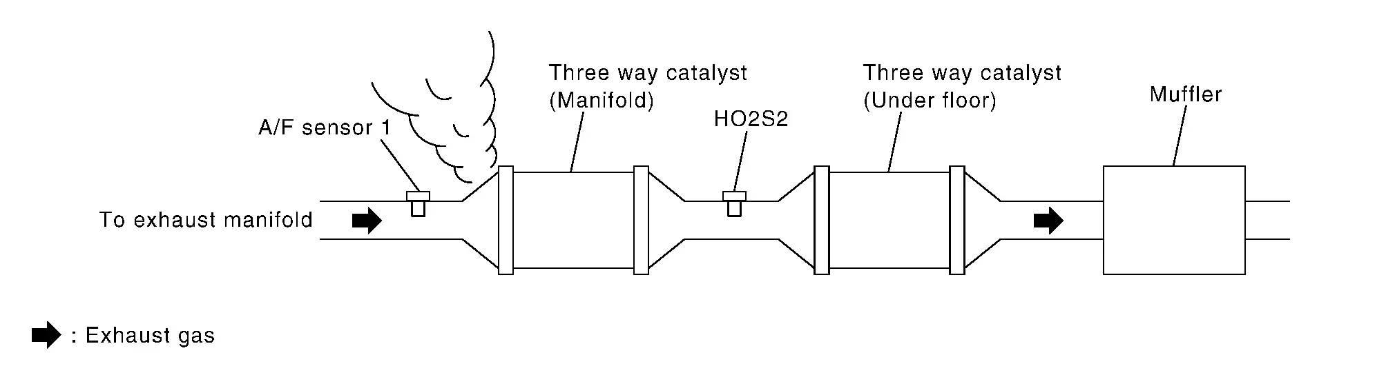
A/F SENSOR1 (B1) (O2 sensor slow response - rich to lean bank 1 sensor 1) |
Diagnosis condition | ŌĆö |
| Signal (terminal) | A/F sensor 1 signal | |||
| Threshold | The response time of a A/F sensor 1 signal delays more than the specified time computed by ECM | |||
| Diagnosis delay time | ŌĆö | |||
POSSIBLE CAUSE
-
Harness or connectors (The A/F sensor 1 circuit is open or shorted.)
-
A/F sensor 1
FAIL-SAFE
Not applicable
DTC Confirmation Procedure
PRECONDITIONING
If DTC Confirmation Procedure has been previously conducted, always perform the following procedure before conducting the next test.
-
Turn ignition switch OFF and wait at least 10 seconds.
-
Turn ignition switch ON.
-
Turn ignition switch OFF and wait at least 10 seconds.
TESTING CONDITION:
Before performing the following procedure, confirm that battery voltage is more than 11 V at idle.
Do you have CONSULT?
YES>>GO TO 2.
NO>>GO TO 6.
PERFORM DTC CONFIRMATION PROCEDURE-1
 With CONSULT
-
Start engine and warm it up to normal operating temperature.
-
Turn ignition switch OFF and wait at least 10 seconds.
-
Turn ignition switch ON.
-
Turn ignition switch OFF and wait at least 10 seconds.
-
Start engine and keep the engine speed between 3,500 and 4,000 rpm for at least 1minute under no load.
-
Let engine idle for 1 minute.
-
Increase the engine speed up to about 3,600 rpm and keep it for 10 seconds.
-
Fully release accelerator pedal and then let engine idle for about 1 minute.
-
Check the items status of ŌĆ£DATA MONITORŌĆØ as follows.
 NOTE:
NOTE:
If ŌĆ£PRSNTŌĆØ changed to ŌĆ£ABSNTŌĆØ, refer to Component Function Check.
Data monitor item Status A/F SEN1 DIAG3 (B1) PRSNT
Is ŌĆ£PRSNTŌĆØ displayed on CONSULT screen?
YES>>GO TO 4.
NO>>GO TO 3.
PERFORM DTC CONFIRMATION PROCEDURE-2
With CONSULT
Perform DTC confirmation procedure-1 again.
Is ŌĆ£PRSNTŌĆØ displayed on CONSULT screen?
YES>>GO TO 4.
NO>>Refer to Component Function Check.
PERFORM DTC CONFIRMATION PROCEDURE-2
With CONSULT
-
Wait for about 20 seconds at idle.
-
Check the items status of ŌĆ£DATA MONITORŌĆØ as follows.
NOTE:
If ŌĆ£CMPLTŌĆØ changed to ŌĆ£INCMPŌĆØ, refer to Component Function Check.
Data monitor item Status A/F SEN1 DIAG1 (B1) CMPLT A/F SEN1 DIAG2 (B1)
Is ŌĆ£CMPLTŌĆØ displayed on CONSULT screen?
YES>>GO TO 5.
NO>>Refer to Component Function Check.
PERFORM SELF-DIAGNOSIS
With CONSULT
Check the ŌĆ£SELF-DIAG RESULTŌĆØ.
Is any DTC detected?
YES>>Proceed to DTC Diagnosis Procedure.
NO>>INSPECTION END
CHECK AIR-FUEL RATIO SELF-LEARNING VALUE
 With GST
-
Start engine and warm it up to normal operating temperature.
-
Select Service $01 with GST.
-
Calculate the total value of ŌĆ£Short term fuel trimŌĆØ and ŌĆ£Long term fuel trimŌĆØ indications.
Is the total percentage within ┬▒15%?
YES>>GO TO 8.
NO>>GO TO 7.
DETECT MALFUNCTIONING PART
Check the following.
-
Intake air leaks
-
Exhaust gas leaks
-
Incorrect fuel pressure
-
Lack of fuel
-
Fuel injector
-
Incorrect PCV hose connection
-
PCV valve
-
Mass air flow sensor
>>
Repair or replace malfunctioning part.
PERFORM DTC CONFIRMATION PROCEDURE
-
Turn ignition switch OFF and wait at least 10 seconds.
-
Turn ignition switch ON.
-
Turn ignition switch OFF and wait at least 10 seconds.
-
Start engine and keep the engine speed between 3,500 and 4,000 rpm for at least 1 minute under no load.
-
Let engine idle for 1 minute.
-
Increase the engine speed up to about 3,600 rpm and keep it for 10 seconds.
-
Fully release accelerator pedal and then let engine idle for about 1 minute.
-
Check 1st trip DTC.
Is 1st trip DTC detected?
YES>>Proceed to DTC Diagnosis Procedure.
NO-1>>To check malfunction symptom before repair: Refer to Intermittent Incident.
NO-2>>Confirmation after repair: INSPECTION END
DTC Diagnosis Procedure
RETIGHTEN A/F SENSOR 1
Loosen and retighten the A/F sensor 1. Refer to Exploded View.
>>
GO TO 2.
CHECK EXHAUST GAS LEAK
-
Start engine and run it at idle.
-
Listen for an exhaust gas leak before three way catalyst (manifold).
Is exhaust gas leak detected?
YES>>Repair or replace.
NO>>GO TO 3.
CHECK FOR INTAKE AIR LEAK
Listen for an intake air leak after the mass air flow sensor.
Is intake air leak detected?
YES>>Repair or replace.
NO>>GO TO 4.
CLEAR THE MIXTURE RATIO SELF-LEARNING VALUE
-
Clear the mixture ratio self-learning value. Refer to Description.
-
Run engine for at least 10 minutes at idle speed.
Is the 1st trip DTC P0171 or P172 detected? Is it difficult to start engine?
YES>>Perform trouble diagnosis for DTC P0171 or P0172. DTC Description or DTC Description
NO>>GO TO 5.
CHECK AIR FUEL RATIO (A/F) SENSOR 1 POWER SUPPLY CIRCUIT
-
Disconnect A/F sensor 1 harness connector.
-
Turn ignition switch ON.
-
Check the voltage between A/F sensor 1 harness connector and ground.
+ ŌĆō Voltage A/F sensor 1 Connector Terminal F18 4 Ground Battery voltage
Is the inspection result normal?
YES>>GO TO 6.
NO>>Repair or replace error-detected parts.
CHECK A/F SENSOR 1 INPUT SIGNAL CIRCUIT
-
Turn ignition switch OFF.
-
Disconnect ECM harness connector.
-
Check the continuity between A/F sensor 1 harness connector and ECM harness connector.
+ ŌĆō Continuity A/F sensor 1 ECM Connector Terminal Connector Terminal F18 1 F72 56 Existed 2 60 -
Check the continuity between A/F sensor 1 harness connector and ground, or ECM harness connector and ground.
+ ŌĆō Continuity A/F sensor 1 Connector Terminal F18 1 Ground Not existed 2 + ŌĆō Continuity ECM Connector Terminal F72 56 Ground Not existed 60 -
Also check harness for short to power.
Is the inspection result normal?
YES>>GO TO 7.
NO>>Repair or replace error-detected parts.
CHECK AIR FUEL RATIO (A/F) SENSOR 1 HEATER
Refer to Component Inspection.
Is the inspection result normal?
YES>>GO TO 8.
NO>>GO TO 11.
CHECK MASS AIR FLOW SENSOR
Refer to Component Inspection.
Is the inspection result normal?
YES>>GO TO 9.
NO>>Replace mass air flow sensor. Refer to Exploded View.
CHECK PCV VALVE
Refer to POSITIVE CRANKCASE VENTILATION : Periodic Maintenance.
Is the inspection result normal?
YES>>GO TO 10.
NO>>Repair or replace PCV valve. Refer to Exploded View.
CHECK INTERMITTENT INCIDENT
Perform Refer to Intermittent Incident.
Is the inspection result normal?
YES>>GO TO 11.
NO>>Repair or replace.
REPLACE AIR FUEL RATIO (A/F) SENSOR 1
Replace air fuel ratio (A/F) sensor 1. Refer to Exploded View.
>>
INSPECTION END
Other materials:
Preparation
Special Service Tool
The actual shapes of TechMate tools may differ from those of special service tools illustrated here.
Tool number
(TechMate No.)
Tool name Description
(NI-39570)
Chassis ear
Locates the noise
(NI-50397)
Squeak and Rattle Kit
Repairs the ca ...
Symptom Diagnosis. Manual Function Does Not Operate
All Component
Diagnosis Procedure
CHECK DRIVER SEAT CONTROL UNIT POWER SUPPLY AND GROUND CIRCUIT
Check driver seat control unit power supply and ground circuit. Refer to Diagnosis Procedure.
Is the inspection result normal?
YES>>
GO TO 2.
NO>>
Repair or replace the malfunctioni ...
Fuel Injector Relay
Component Inspection
CHECK FUEL INJECTOR RELAY
Turn ignition switch OFF.
Remove fuel injector relay. Refer to Component Parts Location.
Check the continuity between fuel injector relay terminals as per the following conditions.
Fuel injector relay Condition Continuity
+ ŌłÆ
...