Nissan Rogue Service Manual: Mudguard
Exploded View
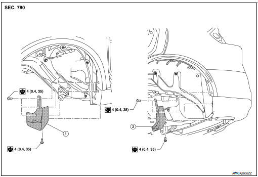
- Front mud guard
- Rear mud guard
Removal and Installation
FRONT MUD GUARD
Removal
Remove front mud guard screws and remove front mud guard.
Installation
Installation is in the reverse order of removal.
REAR MUD GUARD
Removal
Remove rear mud guard screws and remove rear mud guard.
Installation
Installation is in the reverse order of removal.
Exploded View - Center Mudguard
- Center mudguard
 Clip
Clip
 Front
Front
Removal and Installation - Center Mudguard
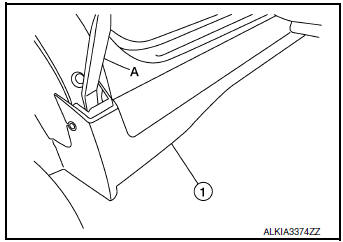
REMOVAL
- Partially remove over fender moldings. Refer to EXT-30, "FRONT OVER FENDER : Exploded View".
- Remove screws (A) from center mudguard (1).
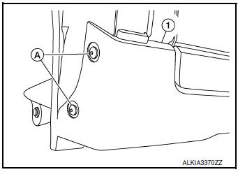
- Remove center mudguard center mudguard bolts (A) from center mudguard
(1).: Front
- Release center mudguard clips with a suitable tool (A) and
remove the center mudguard (1).: Clip
CAUTION: Release clips slowly and carefully.
INSTALLATION
Installation is in the reverse order of removal.
CAUTION:
- Visually check the clips for deformation and damage during installation. Replace with new ones if necessary.
- When installing center mudguard, check that clips are securely placed in body panel holes.
 Over fender
FRONT OVER FENDER
FRONT OVER FENDER : Exploded View
Front fender protector
Front fender
Front over fender molding
Clip
FRONT OVER FENDER : Removal and Installation
REM ...
 Under cover
Exploded View
Floor under cover (RH)
Engine under cover
Floor under cover (LH)
ENGINE UNDER COVER
ENGINE UNDER COVER : Removal and Installation
REMOVAL
Remove engine under ...
Other materials:
P0705 transmission range sensor A
DTC Description
DTC DETECTION LOGIC
DTC
CONSULT screen terms
(Trouble diagnosis content)
DTC detection condition
P0705
T/M RANGE SENSOR A
[Transmission Range Sensor A Circuit (PRNDL
Input)]
When all of the following conditions are satisfied and this state is
...
Preparation
Special Service Tool
The actual shape of the tools may differ from those illustrated here.
Tool number
(TechMate No.)
Tool name
Description
—
(J-39570)
Chassis Ear
Locating the noise
—
(J-50397)
NISSAN Squeak and Rattle Kit
...
Preparation
Special Service Tools
The actual shape of the tools may differ from those illustrated here.
Tool number
(TechMate No.)
Tool name
Description
—
(J-46534)
Trim Tool Set
Removing trim components
...
