Nissan Rogue Service Manual: Meter control switch
Removal and Installation
REMOVAL
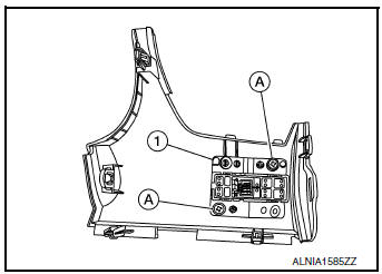
- Remove the instrument finisher (A). Refer to IP-14, "Exploded View".
- Remove the screws (A) and the meter control switch (1).
INSTALLATION
Installation is in the reverse order of removal.
 Combination meter
Removal and Installation
REMOVAL
Disconnect the negative battery terminal. Refer to PG-77, "Removal
and Installation".
Remove the cluster lid A. Refer to IP-20, "R ...
 Unit disassembly and assembly
COMBINATION METER
Exploded View
Combination meter
Combination meter lens
Pawl
Disassembly and Assembly
CAUTION:
Do not touch the display, pointer, inside of combination me ...
Other materials:
How to use the touch-screen
CAUTION
The glass display screen may break if it
is hit with a hard or sharp object. If the
glass screen breaks, do not touch it.
Doing so could result in an injury.
To clean the display, never use a rough
cloth, alcohol, benzine, thinner or any
kind of ...
Periodic maintenance
CVT FLUID
Inspection
FLUID LEAKAGE
Check transaxle surrounding area (oil seal and plug etc.)for fluid
leakage.
If anything is found, repair or replace damaged parts and adjust
CVT fluid level. Refer to TM-192, "Adjustment".
Replacement
Recommended fluid and ...
Combination meter
Removal and Installation
REMOVAL
Disconnect the negative battery terminal. Refer to PG-77, "Removal
and Installation".
Remove the cluster lid A. Refer to IP-20, "Removal and
Installation".
Remove screws (A), from the combination meter (1).
...
