Nissan Rogue Service Manual: Periodic maintenance
CVT FLUID
Inspection
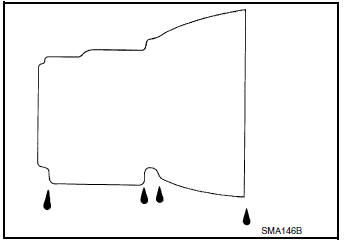
FLUID LEAKAGE
- Check transaxle surrounding area (oil seal and plug etc.)for fluid leakage.
- If anything is found, repair or replace damaged parts and adjust CVT fluid level. Refer to TM-192, "Adjustment".
Replacement
Recommended fluid and fluid capacity : Refer to TM-226, "General Specification".
CAUTION:
- Always use shop paper. Never use shop cloth.
- Replace a drain plug gasket with new ones at the final stage of the operation when installing.
- Use caution when looking into the drain hole as there is a risk of dripping fluid entering the eye.
- After replacement, always perform CVT fluid leakage check.
- Select ŌĆ£Data MonitorŌĆØ in ŌĆ£TRANSMISSIONŌĆØ using CONSULT.
- Select ŌĆ£FLUID TEMPŌĆØ and confirm that the CVT fluid temperature is 40┬░C (104┬░F) or less.
- Check that the selector lever is in the ŌĆ£PŌĆØ position, then completely engage the parking brake.
- Lift up the vehicle.
- Remove the drain plug and drain the CVT fluid from the oil pan. Refer to TM-205, "Exploded View".
- Install the drain plug to oil pan.
CAUTION: Drain plug gasket use the old one.
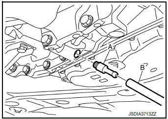
- Remove the overflow plug 1 from converter housing.
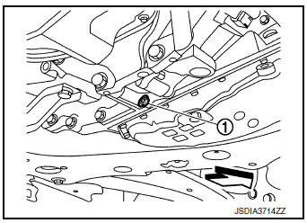
 : Vehicle front
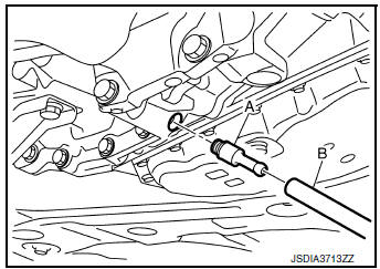
- Install the charging pipe set (KV311039S0) (A) into the overflow
plug hole.
CAUTION: Tighten the charging pipe by hand.
- Install the ATF changer hose (B) to the charging pipe.
CAUTION: Press the ATF changer hose all the way onto the charging pipe until it stops.
- Fill approximately 3 liter (3-1/8 US qt, 2-5/8 lmp qt) of the CVT fluid.
- Remove the ATF changer hose and charging pipe, then install
the overflow plug.
NOTE: Perform this work quickly because CVT fluid leaks.
- Lift down the vehicle.
- Start the engine.
- While depressing the brake pedal, shift the selector lever to the entire position from ŌĆ£PŌĆØ to ŌĆ£LŌĆØ, and shift it to the ŌĆ£PŌĆØ position.
NOTE: Hold the lever at each position for 5 seconds.
- Check that the CONSULT ŌĆ£Data MonitorŌĆØ in ŌĆ£FLUID TEMPŌĆØ is 35┬░C (95┬░F) to 45┬░C (113┬░F).
- Stop the engine.
- Lift up the vehicle.
- Remove the drain plug, and then drain CVT fluid from oil pan.
- Repeat steps 8 to 18 (one time).
- Tighten the drain plug to the specified torque. Refer to TM-205, "Exploded View".
- Remove the overflow plug.
- Install the charging pipe set (KV311039S0) into the overflow plug
hole.
CAUTION: Tighten the charging pipe by hand.
- Install the ATF changer hose to the charging pipe.
CAUTION: Press the ATF changer hose all the way onto the charging pipe until it stops.
- Fill approximately 3 liter (3-1/8 US qt, 2-5/8 lmp qt) of the CVT fluid.
- Remove the ATF changer hose and charging pipe, then install the
overflow plug.
NOTE: Perform this work quickly because CVT fluid leaks.
- Lift down the vehicle.
- Start the engine.
- While depressing the brake pedal, shift the selector lever to the
entire position from ŌĆ£PŌĆØ to ŌĆ£LŌĆØ, and shift it
to the ŌĆ£PŌĆØ position.
NOTE: Hold the lever at each position for 5 seconds.
- Check that the CONSULT ŌĆ£Data MonitorŌĆØ in ŌĆ£FLUID TEMPŌĆØ is 35┬░C (95┬░F) to 45┬░C (113┬░F).
- Lift up the vehicle.
- Remove the overflow plug and confirm that the CVT fluid is drained
from the overflow plug hole.
CAUTION: Perform this work with the vehicle idling.
NOTE: If the CVT fluid is not drained, refer to ŌĆ£AdjustmentŌĆØ and refill with the CVT fluid.
- When the flow of CVT fluid slows to a drip, tighten the overflow
plug to the specified torque. Refer to TM-
205, "Exploded View".
CAUTION: Never reuse O-ring.
- Lift down the vehicle.
- Select ŌĆ£Data MonitorŌĆØ in ŌĆ£TRANSMISSIONŌĆØ using CONSULT.
- Select ŌĆ£CONFORM CVTF DETERIORTNŌĆØ.
- Select ŌĆ£EraseŌĆØ.
- Stop the engine.
Adjustment
Recommended fluid and fluid capacity : Refer to TM-226, "General Specification"
CAUTION:
- During adjustment of the CVT fluid level, check CONSULT so that the oil temperature may be maintained from 35 to 45┬░C (95 to 113┬░F).
- During adjustment of the CVT fluid level, check that the engine speed is maintaining 500 rpm.
- Use caution when looking into the drain hole as there is a risk of dripping fluid entering the eye.
- Check that the selector lever is in the ŌĆ£PŌĆØ position, then completely engage the parking brake.
- Start the engine.
- Adjust the CVT fluid temperature to be approximately 40┬░C (104┬░F).
NOTE: The CVT fluid is largely affected by temperature. Therefore be sure to use CONSULT and check the ŌĆ£FLUID TEMPŌĆØ under ŌĆ£TRANSMISSIONŌĆØ in ŌĆ£Data MonitorŌĆØ while adjusting.
- While depressing the brake pedal, shift the selector lever to the
entire position from ŌĆ£PŌĆØ to ŌĆ£LŌĆØ, and shift it
to the ŌĆ£PŌĆØ position.
NOTE: Hold the lever at each position for 5 seconds.
- Lift up the vehicle.
- Check that there is no CVT fluid leakage.
- Remove the overflow plug 1 from converter housing.
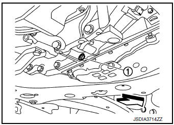
 : Vehicle front
- Install the charging pipe set (KV311039S0) (A) into the overflow
plug hole.
CAUTION: Tighten the charging pipe by hand.
- Install the ATF changer hose (B) to the charging pipe.
CAUTION: Press the ATF changer hose all the way onto the charging pipe until it stops.
- Fill approximately 0.5 liter (1/2 US qt, 1/2 lmp qt) of the CVT fluid.
- Remove the ATF changer hose from the charging pipe, and
check that the CVT fluid drains out from the charging pipe. If it
does not drain out, perform charging again.
CAUTION: Perform this work with the vehicle idling.
- When the flow of CVT fluid slows to a drip, remove the charging pipe from the converter housing.
- Tighten the overflow plug to the specified torque. Refer to
TM-205, "Exploded View".
CAUTION: Never reuse O-ring.
- Lift down the vehicle.
- Stop the engine.
 Symptom diagnosis
CVT CONTROL SYSTEM
Symptom Table
The diagnosis item number indicates the order of check. Start checking
in the order from 1.
Perform diagnoses of symptom table 1 before symptom table 2 ...

Other materials:
Rear disc brake
BRAKE PAD
BRAKE PAD : Exploded View
Sliding pin bolt
Sliding pin bushing
Cylinder body
Inner shim cover
Inner shim
Inner pad
Pad retainer
Torque member
Outer pad
Outer shim
Outer shim cover
Molykote AS-880N
Niglube Rx-2
BRAKE PAD : Re ...
Brake pedal
Exploded View
Rivet
Clevis pin
Brake pedal
Brake pedal pad
Clip
Snap pin
Stop lamp switch
Brake pedal position switch
Removal and Installation
REMOVAL
Remove instrument lower panel LH. Refer to IP-22, "Removal and
Installation". ...
Precaution
Precaution for Supplemental Restraint System
(SRS) "AIR BAG" and "SEAT BELT PRE-TENSIONER"
The Supplemental Restraint System such as ŌĆ£AIR BAGŌĆØ and ŌĆ£SEAT BELT PRE-TENSIONERŌĆØ,
used along
with a front seat belt, helps to reduce the risk or severity of injury to the
dr ...
