Nissan Rogue Service Manual: Rear disc brake
BRAKE PAD
BRAKE PAD : Exploded View
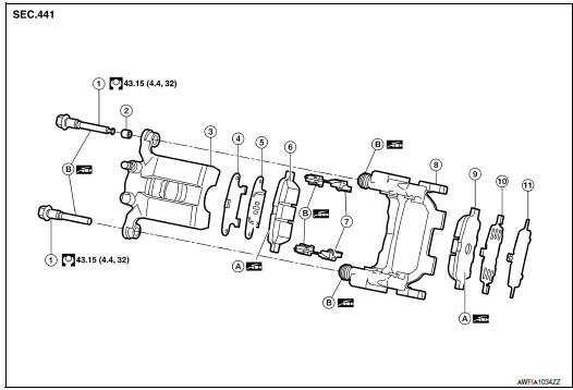
- Sliding pin bolt
- Sliding pin bushing
- Cylinder body
- Inner shim cover
- Inner shim
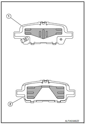
- Inner pad
- Pad retainer
- Torque member
- Outer pad
- Outer shim
- Outer shim cover
- Molykote AS-880N
- Niglube Rx-2
BRAKE PAD : Removal and Installation
REMOVAL
WARNING: Clean dust on brake caliper and brake pad with a vacuum dust collector to minimize the hazards of airborne particles or other material.
CAUTION:
- Do not depress the brake pedal while removing the brake pads because the pistons may pop out.
- It is not necessary to remove bolts on torque member and brake hose except for disassembly or replacement of brake caliper. For brake pad removal, hang brake caliper with a wire so as not to stretch brake hose.
- If brake fluid or grease adheres to the brake caliper or disc brake rotor, quickly wipe it off.
- Partially drain brake fluid from the reservoir tank. Refer to BR-16, "Drain and Refill".
- Remove the rear wheels and tires using power tool.
- Loosen the upper sliding pin bolt and remove the lower sliding pin bolt.
- Using the upper sliding pin bolt as a pivot, swing the brake caliper down from the torque member. Leaving the brake hose attached, support the brake caliper with wire.
- Remove the brake pads, shims, shim covers, pad retainers, and anti-rattle clips from the torque member.
CAUTION:
- Do not reuse the pad retainers and anti-rattle clips.
- Do not damage the piston boot.
- Do not drop the brake pads, shims, or the shim covers.
- Note the position of components during removal to aid with installation.
INSTALLATION
- Install the new pad retainers anti-rattle clips to the torque member.
CAUTION:
- Do not reuse the pad retainers and anti-rattle clips.
- Do not deform the pad retainers.
- Verify that the pad retainers are secured properly to the torque member.
- Apply rubber grease or equivalent to the mating faces between the brake pads and pad retainers. Refer to BR-41, "BRAKE PAD : Exploded View".
- Apply Molykote AS-880N grease or equivalent to the mating
faces between the brake pads, shims and shim covers. Install
components to the brake pad. Refer to BR-41, "BRAKE PAD :
Exploded View".
CAUTION: When installing new brake pads, replace the shims and shim covers.
- Install the brake pads to the torque member.
- Using a suitable tool, press the pistons into the brake caliper.
CAUTION: Do not damage the piston boot.
- Using the upper sliding pin bolt as a pivot, swing the brake caliper up to the torque member.
- Install the lower sliding pin bolts. Tighten all sliding pin bolts to specification. Refer to BR-41, "BRAKE PAD : Exploded View".
- Depress the brake pedal several times and verify that drag does not exist.
- Install the front wheels and tires. Refer to WT-60, "Removal and Installation".
- Check brake fluid level and refill as necessary. Refer to BR-8, "Inspection".
BRAKE CALIPER ASSEMBLY
BRAKE CALIPER ASSEMBLY : Exploded View
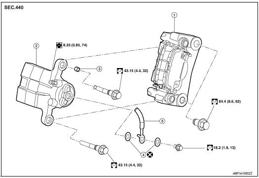
- Torque member
- Brake caliper body
- Sliding pin bushing
- Copper sealing washers
- Brake hose
BRAKE CALIPER ASSEMBLY : Removal and Installation
WARNING: Clean dust on brake caliper and brake pad with a vacuum dust collector to minimize the hazard of airborne particles or other materials
CAUTION:
- Do not depress the brake pedal.
- Do not spill or splash brake fluid on painted areas; it may cause paint damage. If brake fluid is splashed on painted areas, wash it away with water immediately.
- Do not bend, twist or pull the brake hoses and piping.
- Do not reuse drained brake fluid.
NOTE: When removing components such as hoses, tubes/lines, etc., cap or plug openings to prevent fluid from spilling.
REMOVAL
- Remove rear wheels and tires using power tool.
- Secure the disc brake rotor using wheel nuts.
- Remove union bolt, copper sealing washers, and disconnect brake
hose from brake caliper. Discard the
copper sealing washers.
CAUTION: Do not reuse copper sealing washers.
- Remove the torque member bolts. Remove the brake caliper and torque member from the vehicle as an assembly.
- Remove sliding pin bolts and the brake caliper from torque member.
CAUTION: Do not drop brake pads or brake caliper.
INSTALLATION
- Install the brake caliper to torque member and install the sliding pin bolts. Tighten to specification.
- Install the brake caliper and torque member to the vehicle as an assembly. Install the torque member bolts.
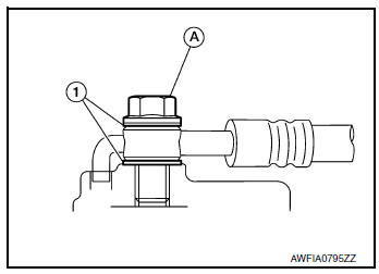
- Assemble the union bolt (A) and the copper sealing washers (1)
to the brake hose and install it as an assembly to the brake caliper.
Align the brake hose L-pin by aligning it with the brake caliper hole, and tighten the union bolt (A) to the specified torque.
CAUTION: Do not reuse copper sealing washers.
- Refill with new brake fluid and perform the air bleeding. Refer to BR-16, "Bleeding Brake System".
CAUTION:
- Do not reuse drained brake fluid.
- Do not spill or splash brake fluid on the disc brake rotor.
- Check the rear disc brakes for drag.
- Install the rear wheels and tires. Refer to WT-60, "Removal and Installation".
 Front disc brake
BRAKE PAD (1 PISTON TYPE)
BRAKE PAD (1 PISTON TYPE) : Exploded View
Torque member
Bushing
Piston boot
Slide pin boot
Slide pin
Piston
Piston seal
Brake caliper ...

Other materials:
Forward-facing child restraint installation
using LATCH
For additional information, refer to all Warnings
and Cautions in the “Child Safety” and “Child
Restraints” sections before installing a child restraint.
NISSAN does not recommend the use of the
lower anchors if the combined weight of the child
and the child restraint exceeds 65 lbs ( ...
P0444, P0445 EVAP canister purge volume control solenoid
DTC Description
DTC DETECTION LOGIC
DTC No.
CONSULT screen terms
(Trouble diagnosis content)
DTC detecting condition
P0444
PURG VOLUME CONT/V
(Evaporative emission system purge control
valve circuit open)
An excessively low voltage signal is sent to ECM through ...
P0181 FTT sensor
DTC Description
DTC DETECTION LOGIC
DTC No.
CONSULT screen terms
(Trouble diagnosis content)
DTC detecting condition
P0181
FTT SENSOR
(Fuel temperature sensor ″A″ circuit range/
performance)
A
Rationally incorrect voltage from the sensor is sent ...
