Nissan Rogue Owners Manual: How to use the vehicle information display
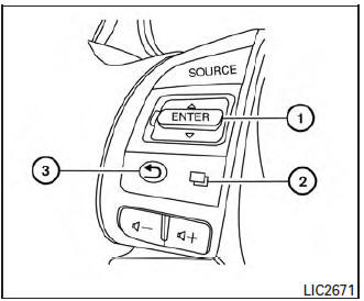
The vehicle information display can be changed
using the buttons  and ENTER located
on
the steering wheel.
and ENTER located
on
the steering wheel.
-
 тАФ navigate through the
items in vehicle
information
ENTER тАФ change or select an item in the
vehicle information display
тАФ navigate through the
items in vehicle
information
ENTER тАФ change or select an item in the
vehicle information display -
 тАФ select/enter the
Vehicle information
menu items or to change from one display
screen to the next (i.e. trip, TPMS, Fuel
economy)
тАФ select/enter the
Vehicle information
menu items or to change from one display
screen to the next (i.e. trip, TPMS, Fuel
economy) -
 тАФ go back to the
previous menu
тАФ go back to the
previous menu
The ENTER and  buttons also
control audio
and control panel functions. For additional information,
refer to тАЬSteering wheel switch for audio controlтАЭ
in тАЬMonitor, climate, audio, phone and voice
recognition systemsтАЭ section of this manual.
buttons also
control audio
and control panel functions. For additional information,
refer to тАЬSteering wheel switch for audio controlтАЭ
in тАЬMonitor, climate, audio, phone and voice
recognition systemsтАЭ section of this manual.
Startup display
When the vehicle in placed in the ON or ACC (if so equipped) position the screens that display in the vehicle information include:
- Active system status (if so equipped)
- Trip computer
- Tire pressure information
- Fuel economy
- Warnings
- Outside air temperature
- Odometer/Twin Trip Odometer
Warnings will only display if there are any present.
For additional information on warnings and indicators, refer to тАЬVehicle information display warnings and indicatorsтАЭ in this section.
To control what items display in the vehicle information display, refer to тАЬMain menu selectionтАЭ in this section.
 Vehicle Information Display
The vehicle information display is located to the
left of the speedometer. It displays such items as:
Vehicle settings
Trip computer information
Drive system warnings an ...
 Settings
The setting mode allows you to change the information
displayed in the vehicle information display:
Driver Assistance
Clock
Meter Settings
Vehicle Settings
M ...
Other materials:
CAN system (type 1)
DTC/CIRCUIT DIAGNOSIS
MAIN LINE BETWEEN IPDM-E AND DLC CIRCUIT
Diagnosis Procedure
1.CHECK CONNECTOR
Turn the ignition switch OFF.
Disconnect the battery cable from the negative terminal.
Check the following terminals and connectors for damage, bend and
loose connecti ...
Power window and door lock/unlock switch RH
Removal and Installation
REMOVAL
Remove the front door pull handle bracket (RH). Refer to INT-15,
"Removal and Installation".
Release pawls using a suitable tool (A) and remove front door
power window and door lock/unlock switch finisher (RH) (1).
: Pawl
D ...
P0605 ECM
DTC Description
DTC DETECTION LOGIC
DTC No.
CONSULT screen terms
(Trouble diagnosis content)
DTC detecting condition
P0605
ECM
[Internal control module read only memory
(ROM) error]
Malfunction in the internal ROM of ECM.
POSSIBLE CAUSE
ECM
FAIL-SAFE
T ...
