Nissan Rogue Service Manual: Front door glass
Exploded View
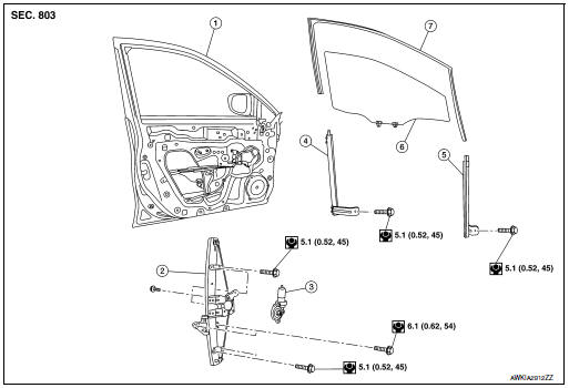
- Front door
- Front regulator
- Front power window motor
- Front door glass rear run
- Front door glass front run
- Front door glass
- Front door glass rubber run
Removal and Installation
REMOVAL
- Remove the front door finisher. Refer to INT-15, "Removal and Installation" .
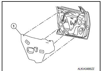
- Remove the vapor barrier (1).
- Temporarily reconnect the main power window and door lock/unlock switch (LH door) or power window and door lock/unlock switch RH (RH door).
- Operate the main power window and door lock/unlock switch (LH door) or front door power window motor and door lock/unlock switch RH (RH door) to raise/lower the front door glass until the front door regulator to front door glass bolts can be seen.
- Remove the front door glass regulator (1) to front door glass bolts (A).
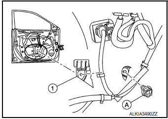
- While holding the front door glass, raise it at the rear end and pull the front door glass out of the sash toward the outside of the door.
INSTALLATION
Installation is in the reverse order of removal.
CAUTION:
- When the main power window and door lock/unlock switch or front power window and door lock/ unlock switch RH is removed it is necessary to perform the initialization procedure. Refer to PWC- 27, "ADDITIONAL SERVICE WHEN REMOVING BATTERY NEGATIVE TERMINAL : Special Repair Requirement".
- Tighten bolts to specification. Refer to GW-14, "Exploded View".
FITTING INSPECTION
- Check that the front door glass is fit securely into the glass run groove.
- Lower the front door glass slightly [approximately 10 to 20 mm (0.39 to 0.79) and check that the clearance to the sash is parallel.If the clearance between the glass and sash is not parallel, loosen the front door glass regulator bolts, front door glass run channel bolts, and glass and run rail bolts to correct the glass position.
 Windshield glass
Exploded View
Mirror base
Spacer
Windshield glass
Windshield glass lower molding
Windshield glass molding
Roof
Cowl top cover
ody side outer
ront pillar finisher
Headli ...
 Front regulator
Exploded View
Front door panel
Front door regulator
Front door power window motor
Front door glass run rear
Front door glass run front
Front door glass
Front door glass rubber ...
Other materials:
Drive belt
QR25DE engine
Crankshaft pulley
Drive belt automatic tensioner pulley
Water pump pulley
Generator pulley
Air conditioner pulley
WARNINGBe sure the ignition switch is placed in the
OFF or LOCK position before servicing
drive belt. The engine cou ...
Satellite radio reception (if so equipped)
When the satellite radio is used for the first time
or the battery has been replaced, the satellite
radio may not work properly. This is not a malfunction.
Wait more than 10 minutes with satellite
radio ON and the vehicle outside of any metal or
large building for satellite radio to receive a ...
Preparation
Special Service Tool
The actual shape of the tools may differ from those illustrated here.
Tool number
(TechMate No.)
Tool name
Description
—
(J-41425-NIS)
Aluminum tube repair kit
Repairing leaks in A/C tube
—
(J-38873-A)
Drive ...
