Nissan Rogue Service Manual: Floor trim
Exploded View
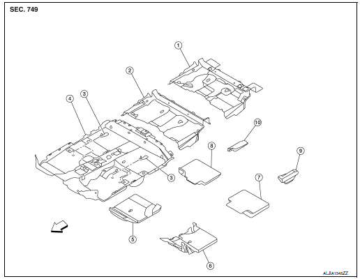
- Rear floor trim (with third row seat)
- Rear floor trim (without third row seat)
- Floor trim hook
- Front floor trim
- Front floor spacer (RH)
- Front floor spacer (LH)
- Rear floor spacer (LH)
- Rear floor spacer (RH)
- Third row floor spacer (LH)
- Third row floor spacer (RH)
 Front
Front
Removal and Installation
REMOVAL - Front Floor Trim
CAUTION: Before servicing, turn the ignition switch off, disconnect both battery cables and wait at least three minutes.
- Disconnect the negative and positive battery terminals, then wait at least three minutes. Refer to PG-77, "Removal and Installation".
- Remove front door welts (LH/RH). Refer to INT-23, "BODY SIDE WELT : Removal and Installation - Front Door Welt".
- Remove rear door welts (LH/RH). Refer to INT-23, "BODY SIDE WELT : Removal and Installation - Rear Door Welt".
- Remove driver and passenger seat (LH/RH). Refer to SE-32, "DRIVER SIDE : Removal and Installation".
- Remove rear seat. Refer to SE-39, "Removal and Installation".
- Disconnect harness connectors from seatbelt pretensioners.
- Remove dash side finisher (LH/RH). Refer to INT-24, "DASH SIDE FINISHER : Removal and Installation".
- Remove cvt shift selector. Refer to TM-194, "Removal and Installation".
- Remove center pillar upper finisher (LH/RH). Refer to INT-21, "CENTER PILLAR UPPER FINISHER : Removal and Installation".
- Remove the front floor connecting ducts (LH/RH). Refer to VTL-10, "FRONT FLOOR DUCT : Removal and Installation - Front Floor Connecting Duct".
- Disconnect front parking brake cable from rear parking brake cable and remove bolts from parking brake cable hold down. Refer to PB-7, "Exploded View".
- Disconnect heating and cooling unit assembly drain hose from floor.
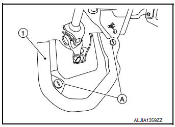
- Release clips (A) using a suitable tool and remove steering joint floor cover (1).
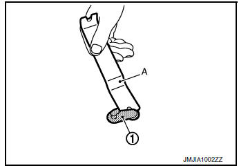
- Remove floor trim hooks (1) using a suitable tool (A) and front floor trim.
- Remove the following parts (if necessary).
- Front floor spacer (LH/RH)
- Rear floor spacer (LH/RH)
INSTALLATION
Installation is in the reverse order of removal.
REMOVAL - Rear Floor Trim
CAUTION: Before servicing, turn the ignition switch off, disconnect both battery cables and wait at least three minutes.
- Disconnect the negative and positive battery terminals, then wait at least three minutes. Refer to PG-77, "Removal and Installation".
- Partially remove front door welts (LH/RH). Refer to INT-23, "BODY SIDE WELT : Removal and Installation - Front Door Welt".
- Partially remove rear door welts (LH/RH). Refer to INT-23, "BODY SIDE WELT : Removal and Installation - Rear Door Welt".
- Remove rear seat assembly. Refer to SE-39, "Removal and Installation".
- Remove seat belt lower anchor bolt (LH/RH).
CAUTION: Before removing the seat belt lower anchor bolt, note the positions of washers and spacers for correct installation.
- Remove luggage side lower finisher (LH/RH). Refer to INT-34, "LUGGAGE SIDE LOWER FINISHER : Removal and Installation - With Third Row Seat".
- Remove third row seat assembly (if equipped). Refer to SE-43, "Removal and Installation".
- Remove rear floor trim.
INSTALLATION
Installation is in the reverse order of removal.
 Body side trim
Exploded View
Front pillar finisher
Front body side welt
Center pillar upper finisher
Rear body side welt
Rear kicking plate
Seat belt cover
Center pillar lower fin ...
 Headlining
Exploded View
WITHOUT MOONROOF
Map lamp assembly bracket
Headlining
Assist grip (without coat hanger)
Map lamp assembly
Sun visor holder (LH/RH)
Sun visor (RH)
&nb ...
Other materials:
Diagnosis system (EPS control unit)
CONSULT Function
FUNCTION
CONSULT can display each diagnostic item using the diagnostic test modes
shown following
Diagnostic test mode
Function
ECU identification
The part number stored in the control unit can be read.
Self diagnostic result
Self-diagnosti ...
NISSAN Voice Recognition System
(if so equipped)
The NISSAN Voice Recognition system allows
hands-free operation of the systems equipped on
this vehicle, such as the phone and navigation
systems.
To operate NISSAN Voice Recognition, press
the button located on the steering
wheel.
When prompted, speak the command for the
system you wi ...
Booster seats
Precautions on booster seats
WARNINGIf a booster seat and seat belt are not used
properly, the risk of a child being injured in
a sudden stop or collision greatly
increases:
Make sure the shoulder portion of
the belt is away from the child’s face
and neck and ...
