Nissan Rogue Service Manual: ECU diagnosis information
AUDIO UNIT
Reference Value
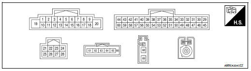
TERMINAL LAYOUT
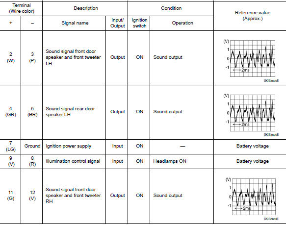
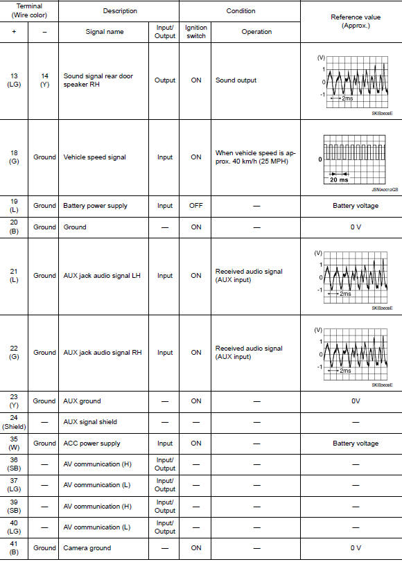
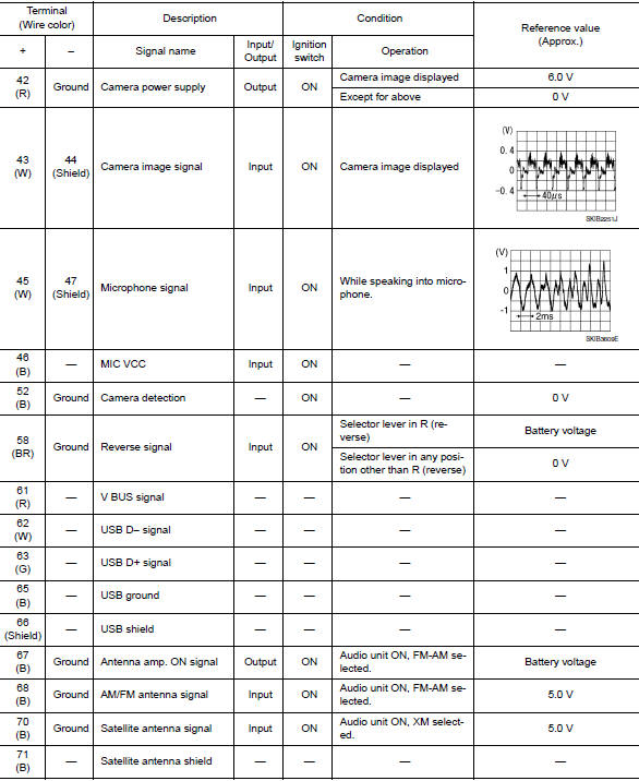
PHYSICAL VALUES
 System description
COMPONENT PARTS
Component Parts Location
Center of back door
No.
Component
Function
1
Rod antenna
Refer to AV-14, "Rod Antenna, Antenna Amp., S ...
 Wiring diagram
DISPLAY AUDIO
Wiring Diagram
...
Other materials:
NISSAN Intelligent Key® Operation
NISSAN Intelligent Key® Operation
You can lock or unlock the doors without taking
the Intelligent Key out of your pocket or bag.
When you carry the Intelligent Key with you, you
can lock or unlock all doors by pushing the door
handle request switch within the range of operation.
Loc ...
EVAP canister
Exploded View
EVAP control system pressure sensor
O-ring
EVAP canister
EVAP canister vent control valve
EVAP canister vent control valve hose
EVAP vent line
EVAP canister purge hose
Clamp
Front
Removal and Installation
NOTE:
The EVAP canister vent control val ...
Engine oil
Inspection
ENGINE OIL LEVEL
NOTE:
Before starting engine, put vehicle horizontally and check the engine oil level.
If engine is already started, stop
it and allow 5 minutes before checking.
Pull out oil level gauge and wipe it clean.
Insert oil level gauge and check the engin ...
