Nissan Rogue Service Manual: System description
COMPONENT PARTS
Component Parts Location
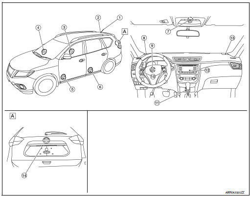
- Center of back door
|
No. |
Component |
Function |
| 1 | Rod antenna | Refer to AV-14, "Rod Antenna, Antenna Amp., Satellite Antenna and Antenna Feeder". |
| 2 | Antenna base (antenna amp. and satellite antenna) | |
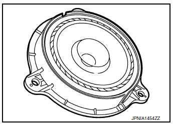
| 3 | Rear door speaker RH | Refer to AV-12, "Speakers". |
| 4 | Front door speaker RH | |
| 5 | Front door speaker LH | |
| 6 | Rear door speaker LH | |
| 7 | Microphone | Refer to AV-13, "Microphone". |
| 8 | Front tweeter LH | Refer to AV-12, "Speakers". |
| 9 | Steering angle sensor | Refer to AV-14, "Steering Angle Sensor". |
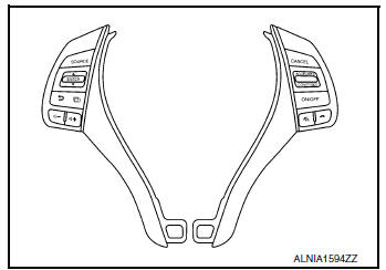
| 10 | Steering switches | Refer to AV-13, "Steering Switches". |
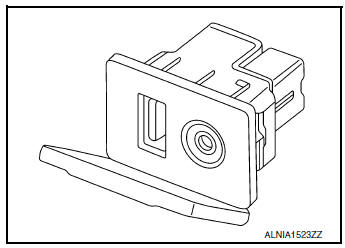
| 11 | USB interface and AUX in jack | Refer to AV-13, "USB Interface and AUX in Jack". |
| 12 | Audio unit | Refer to AV-12, "Audio Unit". |
| 13 | Front tweeter RH | Refer to AV-12, "Speakers". |
| 14 | Rear view camera | Refer to AV-13, "Rear View Camera". |
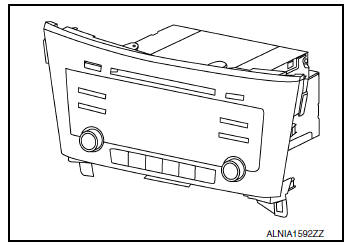
Audio Unit
Description
- AM/FM electronic tuner radio, CD drive and camera controller are integrated into the audio unit.
- The display can show audio status and rear view monitor images.
- Music files stored in iPod®*/USB memory can be played using the separate USB connector.
- Music files stored in an external audio device can be played using the separate AUX in jack.
Speakers
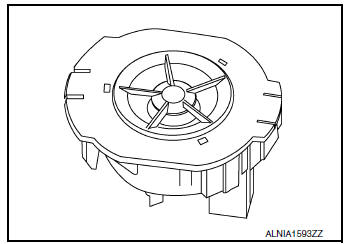
FRONT TWEETER
- 2.5 cm (1 in) tweeters are installed in the top front corners of the instrument panel.
- Sound signals are input from the audio unit to output high range sounds.
FRONT DOOR SPEAKER
- 16.5 cm (6.5 in) speakers are installed in the bottom of the front doors.
- Sound signals are input from the audio unit to output high, mid and low range sounds.
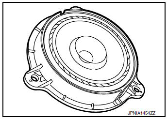
REAR DOOR SPEAKER
- 16.5 cm (6.5 in) speakers are installed in the bottom of the rear doors.
- Sound signals are input from the audio unit to output high, mid and low range sounds.
USB Interface and AUX in Jack
- USB Interface and AUX in jack is installed in the console.
- iPod® and USB memory can be connected to the audio unit through the USB interface.
- An external audio device can be connected to the audio unit through the AUX in jack.
Steering Switches
- Steering switches are installed in the steering wheel.
- Operations for audio and hands-free phone are possible.
- Switches are connected to the combination meter.
- Combination meter is connected to the audio unit via AV communication
Microphone
- The microphone is installed in the roof in the map lamp assembly.
- Power is supplied from the audio unit.
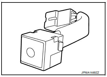
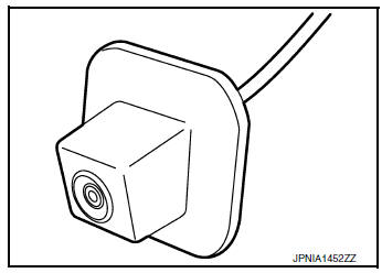
Rear View Camera
- The rear view camera is installed to the back door finisher.
- Power is supplied from the audio unit.
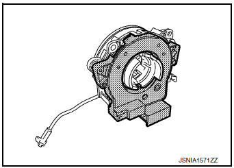
Steering Angle Sensor
- Steering sensor is installed to the spiral cable.
- Steering angle sends the steering signal necessary for predictive course line via CAN communication.
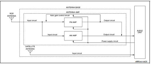
Rod Antenna, Antenna Amp., Satellite Antenna and Antenna Feeder
RADIO ANTENNA AND SATELLITE ANTENNA
AM/FM radio rod antenna, antenna base and satellite antenna are located on the rear of the roof. The antenna amp. and satellite antenna are built into the antenna base.
ANTENNA FEEDER LAYOUT
- Antenna base (antenna amp. and satellite antenna)
- Rod Antenna
- M503
- M502
- M130, M501
- M129, M500
- M126
- M124
SYSTEM
System Description
SYSTEM DIAGRAM
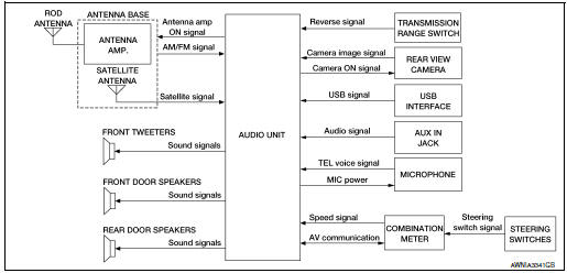
AUDIO SYSTEM
The audio system consists of the following components
- Audio unit
- Front tweeters
- Front door speakers
- Rear door speakers
- USB interface
- AUX in jack
- Steering switches
- Antenna base (rod antenna, antenna amp. and satellite antenna)
When the audio system is on, AM/FM signals received by the rod antenna are amplified by the antenna amp.
and sent to the audio unit. The audio unit then sends audio signals to the front tweeters, front door speakers and rear door speakers.
Refer to Owner's Manual for audio system operating instructions.
HANDS-FREE PHONE SYSTEM
- Bluetooth® control is built into audio unit.
- The connection between cellular phone and audio unit is performed with Bluetooth® communication.
- The voice guidance signal is input from the audio unit and output to the front speakers when operating the cellular phone.
When A Call Is Originated
- Spoken voice sound output from the microphone (microphone signal) is input to audio unit.
- Audio unit outputs to cellular phone with Bluetooth® communication as a TEL voice signal.
- Voice sound is then heard at the other party.
When Receiving A Call
- Voice sound is input to own cellular phone from the other party.
- TEL voice signal is input to audio unit by establishing Bluetooth® communication from cellular phone, and the signal is output to front speakers.
SPEED SENSITIVE VOLUME SYSTEM
Volume level of this system goes up and down automatically in proportion to the vehicle speed. The control level can be selected by the customer. Refer to Owner's Manual for operating instructions.
REAR VIEW MONITOR FUNCTION
Camera Image Operation Principle
- The audio unit supplies power to the rear view camera when receiving a reverse signal.
- The rear view camera transmits camera images to the audio unit when power is supplied from the audio unit.
- The audio unit combines a warning message and fixed guide lines with an image received from the rear view camera to display a rear view camera image on the screen.
DIAGNOSIS SYSTEM (AUDIO UNIT)
Description
The audio unit on board diagnosis performs the functions listed in the table below:
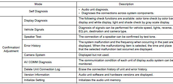
On Board Diagnosis Function
METHOD OF STARTING
- Turn the ignition ON.
- Turn the audio system OFF.
- While pressing the preset 1 button, turn the volume control dial clockwise or counterclockwise for 40 clicks or more. Shifting from current screen to previous screen is performed by pressing BACK button.
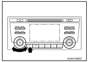
- The trouble diagnosis initial screen is displayed, and Self Diagnosis or Confirmation/Adjustment can be selected.
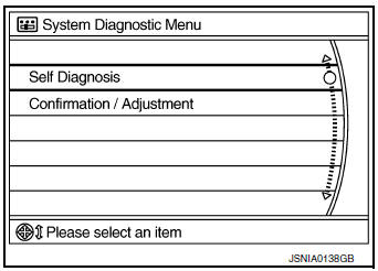
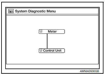
SELF DIAGNOSIS MODE
Audio Unit Self Diagnosis
- Select Self Diagnosis.
- Self diagnosis screen is displayed. The bar graph visible in center of screen indicates progress of self diagnosis.
- Diagnosis results are displayed after the self diagnosis is
completed.
The unit names and the connection lines are color coded according to the diagnostic results.
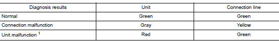
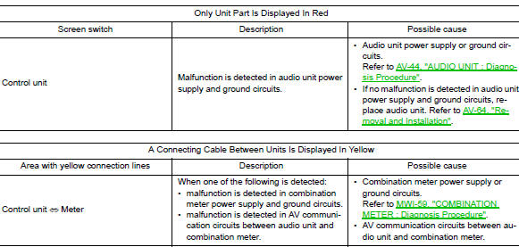
1: Control unit (audio unit) is displayed in red.
- Replace audio unit if Self Diagnosis did not run because control unit malfunction is indicated. The symptom is audio unit internal error. Refer to AV-64, "Removal and Installation".
- If multiple errors occur at the same time for a single unit, the screen switch colors are determined according to the following order of priority: red > gray.
- Comments of self diagnosis results can be viewed in the diagnosis result screen.
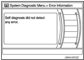
Audio Unit Self Diagnosis Results
Audio Unit Confirmation/Adjustment
- Select Confirmation/Adjustment.
- Select each switch on the Confirmation/Adjustment screen to display the relevant trouble diagnosis screen. Press the BACK switch to return to the initial Confirmation/Adjustment screen.
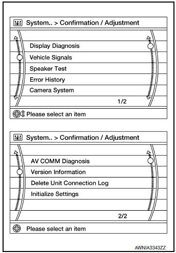
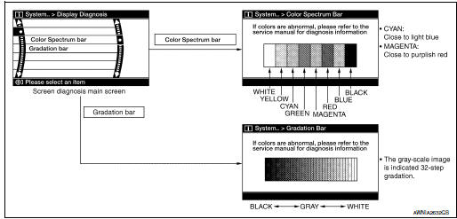
Display Diagnosis
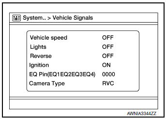
Vehicle Signals
A comparison check can be made of each actual vehicle signal and the signals recognized by the system.
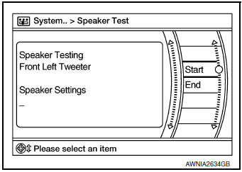
Speaker Test
Select Speaker Test to display the Speaker Diagnosis screen. Press Start to generate a test tone in a speaker. Press Start again to generate a test tone in the next speaker. Press End to stop the test tones.
Error History
The self diagnosis results are judged depending on whether any error occurs from when Self Diagnosis is selected until the self diagnosis results are displayed.
However, the diagnosis results are judged normal if an error has occurred before the ignition switch is turned ON and then no error has occurred until the self diagnosis start. Check the Error Record to detect any error that may have occurred before the self diagnosis start because of this situation.
The frequency of occurrence is displayed in a count up manner. The actual count up method differs depending on the error item.
Count up method A
- The counter is set to 40 if an error occurs. 1 is subtracted from the counter if the condition is normal at a next ignition ON cycle.
- The counter lower limit is 1. The counter can be reset (no error record display) with the Delete log switch.
Count up method B
- The counter increases by 1 if an error occurs when ignition switch is ON. The counter will not decrease even if the condition is normal at the next ignition ON cycle.
- The counter upper limit is 50. Any counts exceeding 50 are ignored. The counter can be reset (no error record display) with the Delete log switch.
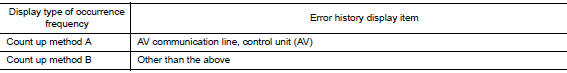
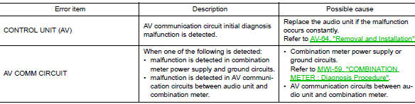
Error item
Some error items may be displayed simultaneously according to the cause. If some error items are displayed simultaneously, the detection of the cause can be performed by the combination of display items
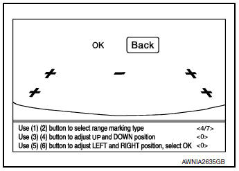
Camera System
This mode is used to adjust the guide line display position of the rear view camera.
AV COMM Diagnosis
- Displays the communication status between audio unit (master unit) and each unit.
- The error counter displays OK if any malfunction was not detected
in the past and displays 0 if a malfunction is detected. It increases
by 1 if the condition is normal at the next ignition switch ON cycle.
The upper limit of the counter is 39.
- The error counter is erased if Reset is pressed.
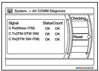
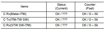
NOTE: “???” indicates UNKWN.
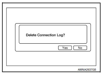
Delete Unit Connection Log
Deletes any unit connection records and error records from the audio unit memory (clears the records of the unit that has been removed).
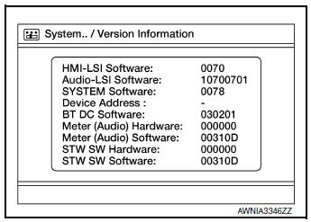
Version Information
Displays audio unit software and hardware version numbers.
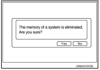
Initialize Settings
Deletes data stored from the audio unit.
 Preparation
Special Service Tool
The actual shape of the tools may differ from those illustrated here.
Tool number
(TechMate No.)
Tool name
Description
—
(J-46534)
Trim ...
 ECU diagnosis information
AUDIO UNIT
Reference Value
TERMINAL LAYOUT
PHYSICAL VALUES
...
Other materials:
Preparation
Special Service Tools
The actual shape of the tools may differ from those illustrated here.
Tool number
(TechMate No.)
Tool name
Description
—
(J-44372)
Pull gauge
Measuring steering wheel turning force, rack
sliding force and ball joint swinging ...
Differential side oil seal
Exploded View
Transaxle assembly
Differential side oil seal (left side)
Differential side oil seal (right side)
(FWD models only)
: Always replace after every
disassembly.
: Apply CVT fluid
Removal and Installation
REMOVAL
NOTE:
When removing components such as hoses, tubes ...
Ambient sensor signal circuit
Description
It detects outside air temperature and converts it into a resistance value
which is then input into the combination
meter.
Diagnosis Procedure
Regarding Wiring Diagram information, refer to MWI-32, "Wiring Diagram".
1.CHECK AMBIENT SENSOR SIGNAL CIRCUIT
Turn ig ...
