Nissan Rogue (T33) 2021-Present Owner’s Manual & User Guide: Flat tire
Tire Pressure Monitoring System (TPMS)
This vehicle is equipped with the Tire Pressure Monitoring System (TPMS), which continuously monitors the air pressure in all tires except the spare. If the low tire pressure warning light illuminates and the “Tire Pressure Low – Add Air” message appears in the vehicle information display, at least one tire is significantly under-inflated. When tire pressure drops below the recommended level and the vehicle is driven above 16 MPH (25 km/h), the TPMS activates and provides a warning.
WARNING
- If the low tire pressure warning light comes on while driving, avoid sudden steering or abrupt braking. Reduce speed carefully, pull off the road to a safe location, and stop the vehicle as soon as possible. Driving with significantly under-inflated tires can permanently damage the tires, increase the risk of tire failure, and may lead to an accident causing serious personal injury.
- After stopping, check the pressure of all four tires and adjust them to the recommended COLD tire pressure listed on the Tire and Loading Information label. This will turn the warning light OFF. If the warning light stays on even after adjusting air pressure, one of the tires may be flat and must be replaced with the spare tire promptly.
- The spare tire is not equipped with TPMS. When a spare tire is installed or when a wheel without a sensor is mounted, the TPMS will not operate. In this case, the low tire pressure warning light will flash for about one minute and then stay illuminated. Replace the tire and/or have the TPMS reset as soon as possible.
It is recommended that these services be performed by a NISSAN dealer. - Do not install tires of a size or type different from those originally specified by NISSAN, as doing so may affect TPMS performance.
- Do not inject tire sealants or aerosol puncture repair substances into any tire, as these can cause TPMS sensor malfunction.
Changing a flat tire
Basic information
If you experience a flat tire, follow the procedure below to safely replace it.
Stopping the vehicle
1. Safely move your vehicle off the roadway and away from traffic.
2. Turn on the hazard warning flashers.
3. Park on a flat, level surface and apply the parking brake.
4. Push the park button to shift into the P (Park) position.
5. Turn off the engine.
6. Raise the hood to alert other drivers and signal roadside assistance personnel.
7. Have all passengers exit the vehicle and stand in a safe area away from traffic.
WARNING
- Ensure the parking brake is fully applied and the vehicle is securely in P (Park).
- Never attempt to change a tire on a slope, ice, or slippery surfaces. This is extremely dangerous.
- If traffic is passing close to your vehicle, do not attempt to change the tire. Wait for professional assistance.
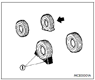
Blocking wheels
Place suitable blocks 1 both in front of and behind the wheel opposite the flat tire. This prevents the vehicle from rolling while it is raised by the jack.
WARNING
Always block the wheels. Failure to do so may allow the vehicle to move and could cause personal injury.
Models with adjustable luggage floor
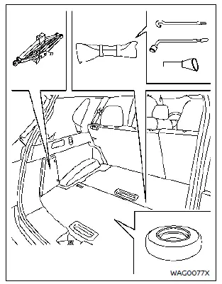
Getting the spare tire and tools
The jack, tools, and spare tire are stored in the luggage compartment.
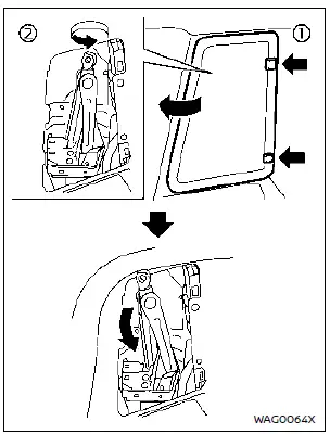
To remove the jack:
1. Open the storage door by pressing both release tabs.
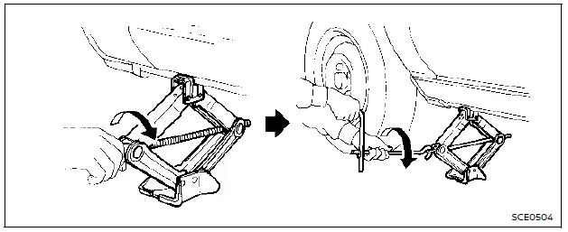
2. Turn the jack lever counterclockwise and remove the jack slowly.
When storing the jack, place it back carefully, then turn the lever clockwise to secure it.
CAUTION
Be careful not to injure your hands when removing the jack.
NOTE:
- Do not overtighten the jack lever when storing the jack. This may deform the mounting area.
- Ensure the jack does not contact interior trim parts to avoid damage.
Models with adjustable luggage floor (example)
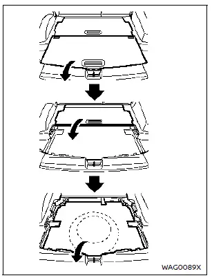
Removing the spare tire and tools
The spare tire and tools are located beneath the luggage floorboard(s).
To access them:
1. Remove the luggage floorboard(s).
– Models with adjustable floor: Unlock before lifting the rear (outer) board.
– Models with single board: Release the retainer pins.
2. Remove the floor carpet (if equipped). Then remove the tool bag from the storage compartment.
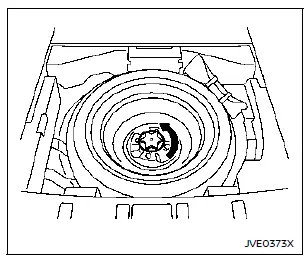
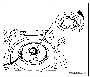
Remove the spare tire by loosening and removing the holding clamp.
Example
Removing the spare tire with subwoofer (if equipped)
1. Turn the bolt counterclockwise to loosen it.
2. Remove the bolt completely.
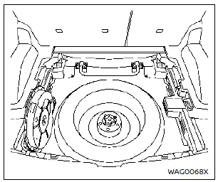
Example
3. Place the subwoofer in the left corner of the cargo area.
4. Remove the spare tire.
5. After installing the spare in place of the flat tire, store the flat tire in the spare tire area.
6. Place the subwoofer inside the flat tire.
7. Tighten the bolt by turning it clockwise.
Jacking up the vehicle and removing the damaged tire
WARNING
- Never go under the vehicle when it is supported only by a jack. Use safety stands if you need to work underneath.
- Use only the vehicle’s supplied jack when lifting your Nissan. It is designed for this vehicle only.
- Use only the specified jack-up points. Do not lift the vehicle at any other location.
- Do not raise the vehicle higher than necessary.
- Never place blocks or objects under the jack.
- Do not start or run the engine while the vehicle is raised on the jack.
- No passengers should remain in the vehicle while it is on the jack.
Carefully follow the label on the jack and these instructions.
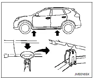
Jack-up point
1. Position the jack under the jack-up point so that the top of the jack aligns with the two notches. Ensure the jack head groove fits properly between the notches.
The jack must be on firm, level ground.
2. Loosen each wheel nut 1–2 turns using the wheel nut wrench. Do not fully remove the nuts yet.
3. Holding the jack lever and rod securely with both hands, raise the vehicle until the tire clears the ground.
Then remove the wheel nuts completely and take off the tire.
Installing the spare tire
The spare tire is designed for emergency use.
1. Clean any mud or dirt from the mounting surface between the wheel and the hub.
2. Carefully place the spare tire onto the hub and tighten the wheel nuts by hand until they are finger tight.
Make sure all wheel nuts sit flat against the wheel surface.
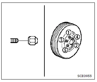
3. Using the wheel nut wrench, tighten the nuts alternately and evenly in the order shown (1, 2, 3, 4, 5). Repeat the tightening sequence more than two times until all nuts are snug.
4. Lower the vehicle slowly until the tire just touches the ground. Then use the wheel nut wrench to fully tighten the wheel nuts securely, again following the illustrated tightening order.
Lower the vehicle completely.
WARNING
- Incorrect or improperly tightened wheel nuts can cause the wheel to become loose or fall off, leading to an accident.
- Do not apply oil or grease to the wheel studs or nuts. Lubricants can cause the nuts to loosen.
- Retighten the wheel nuts after driving 600 miles (1,000 km), including after replacing a flat tire.
- Tighten the wheel nuts to the specified torque as soon as possible using a torque wrench.
Wheel nut tightening torque: 80 ft-lb (108 N·m)
The wheel nuts must always remain tightened to the specified torque. It is recommended to check and tighten them to specification at each lubrication interval.
- Adjust the tire pressure to the recommended COLD pressure.
COLD pressure:
When the vehicle has been parked for at least 3 hours or driven less than 1 mile (1.6 km).
The recommended COLD tire pressures are listed on the Tire and Loading Information label located on the driver-side center pillar.
Stowing the damaged tire and tools
1. Securely store the jack, tools, and damaged tire in the designated storage area.
2. Reinstall the luggage board(s) and cover.
3. Close the liftgate.
WARNING
- Always ensure that the spare tire and jacking equipment are securely stored after use. Loose items can become dangerous projectiles during sudden stops or accidents.
- The spare tire is intended for emergency use only.
Other materials:
Fonctionnement du système LDW
Témoin LDW (affiché sur l’écran d’informations du véhicule)
Écran d’informations du véhicule
Commandes au volant (côté gauche)
Le système LDW du Nissan Rogue active la fonction d’alerte sortie de voie lorsque la vitesse du véhicule atteint environ 60 km/h (37 mi ...
Guide de dépistage des pannes courantes
Informations de base
Plusieurs syst√®mes d‚Äôaide √Ý la conduite du Nissan Rogue utilisent des composants communs, tels que la cam√©ra avant ou les capteurs radar, afin d‚Äôassurer leur fonctionnement coordonn√©. Lorsqu‚Äôun message contextuel d‚Äôavertissement s‚Äôaffiche sur l‚Äô√©cran d‚Äôinform ...
Ascd. Removal and Installation. Ascd Steering Switch
Ascd Steering Switch
Removal and Installation
REMOVALFor servicing the Japan production ASCD steering
switch, service the Japan production steering wheel. Refer to Removal
and Installation.NOTE:
The Japan production ASCD steering switch is serviced as
an assembly with the Japan production s ...