Nissan Rogue Service Manual: ECU diagnosis information
DIAGNOSIS SENSOR UNIT
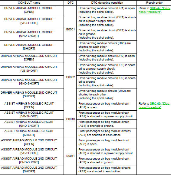
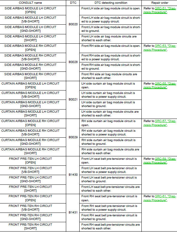
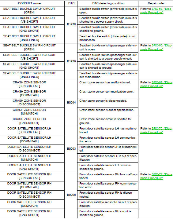
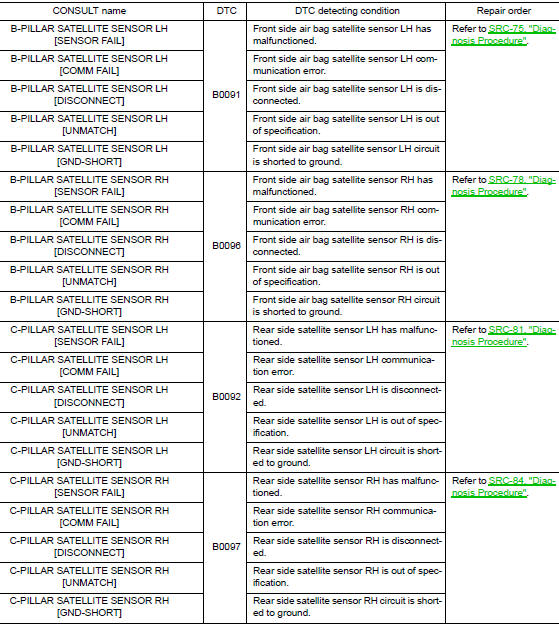
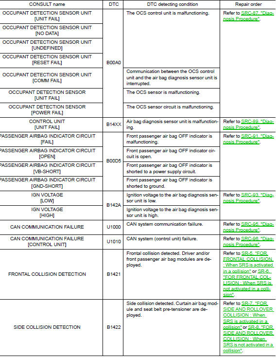
DTC Index
DIAGNOSTIC CODE CHART
NOTE: Follow the procedures in numerical order when repairing malfunctioning parts. Confirm whether malfunction is eliminated using air bag warning lamp or CONSULT each time repair is finished. If malfunction is still observed, proceed to the next step. When malfunction is eliminated, further repair work is not required.
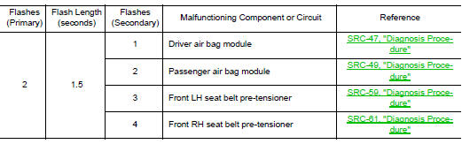
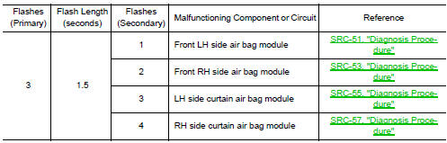
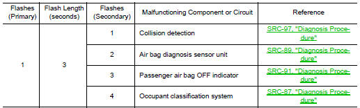
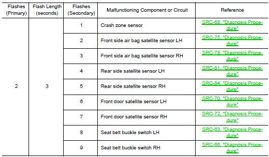
Flash Code Index
WARNING LAMP FLASH CODE CHART
- Put the vehicle in Diagnosis Mode. Refer to SRC-16, "On Board Diagnosis Function".
- All codes are proceded by a seven second "holding" flash.
- Identify how many primary flashes are displayed as well as the length of each primary flash.
- Refer to the tables and examples below to determine which SRS subsystem the code belongs to.
- Count the short secondary flashes that follow the primary flashes.
- Match the correct flashing pattern to the malfunctioning component and perform the Diagnosis Procedure.
Refer to the illustrations below for an example of each flashing pattern.
Front subsystem

Side subsystem
Air bag subsystem
Sensor subsystem
 Diagnosis system (air bag)
Description
CAUTION:
Never use electrical test equipment on any circuit related to
the SRS unless instructed in this Service
Manual. SRS wiring harnesses can be identified by yellow an ...
 Wiring diagram
SRS AIR BAG SYSTEM
Wiring Diagram
...
Other materials:
P0037, P0038 HO2S2 heater
DTC Description
DTC DETECTION LOGIC
DTC No.
CONSULT screen terms
(Trouble diagnosis content)
DTC detecting condition
P0037
HO2S2 HTR (B1)
(HO2S heater control circuit low bank 1
sensor 2)
The current amperage in the heated oxygen sensor 2 heater circuit is
...
System description
COMPONENT PARTS
Component Parts Location
Air bag diagnosis sensor unit
AV control unit
Around view monitor control unit
Chassis control module
ABS actuator and electric unit (control
unit)
• A/C auto amp. (With auto A/C)
• Front air control (Without auto A/
C)
...
ECU diagnosis information
A/C AUTO AMP.
Reference Value
VALUES ON THE DIAGNOSIS TOOL
TERMINAL LAYOUT
PHYSICAL VALUES
DTC Inspection Priority Chart
If some DTCs are displayed at the same time, perform inspections one by one
based on the following priority
chart.
Priority
Det ...
