Nissan Rogue Service Manual: DTC/circuit diagnosis
SPORT MODE SWITCH
Component Function Check
1. CHECK SPORT MODE SWITCH OPERATION
- Turn ignition switch ON.
- Check SPORT mode indicator lamp turns ON/OFF on combination meter when turn SPORT mode switch ON/OFF.
Is the inspection result normal? YES >> INSPECTION END
NO >> Proceed to DMS-13, "Diagnosis Procedure".
Diagnosis Procedure
1.CHECK SPORT MODE SWITCH CIRCUIT
- Turn ignition switch OFF.
- Disconnect SPORT mode switch harness connector.
- Turn ignition switch ON.
- Check voltage between SPORT mode switch harness connector terminals.
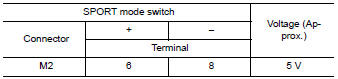
Is the inspection result normal? YES >> GO TO 6.
NO >> GO TO 2.
2.CHECK GROUND CIRCUIT
- Turn ignition switch OFF.
- Check the continuity between SPORT mode switch harness connector and ground.
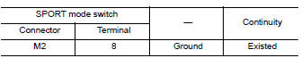
Is the inspection result normal? YES >> GO TO 3.
NO >> Repair or replace damaged parts.
3.CHECK CIRCUIT BETWEEN COMBINATION METER AND SPORT MODE SWITCH (1)
- Disconnect combination meter harness connector M76.
- Check continuity between combination meter harness connector terminal and SPORT mode switch harness connector terminal.
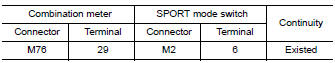
Is the inspection result normal? YES >> GO TO 4.
NO >> Repair or replace damaged parts.
4.CHECK CIRCUIT BETWEEN COMBINATION METER AND SPORT MODE SWITCH (2)
Check continuity between combination meter harness connector terminal and SPORT mode switch harness connector terminal.
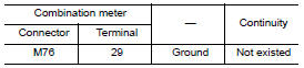
Is the inspection result normal? YES >> GO TO 5.
NO >> Repair or replace damaged parts.
5.CHECK COMBINATION METER INPUT/OUTPUT SIGNAL
- Connect all of disconnected connectors.
- Check input/output signal of combination meter. Refer to MWI-24, "Reference Value".
Is the inspection result normal? YES >> Check intermittent incident. Refer to GI-41, "Intermittent Incident".
NO >> Replace combination meter. Refer to MWI-82, "Removal and Installation".
6.CHECK SPORT MODE SWITCH
Check SPORT mode switch. Refer to DMS-14, "Component Inspection".
Is the inspection result normal? YES >> Check intermittent incident. Refer to GI-41, "Intermittent Incident".
NO >> Replace SPORT mode switch. Refer to DMS-16, "Removal and Installation".
Component Inspection
1.CHECK SPORT MODE SWITCH
Check continuity between SPORT mode switch connector terminals.
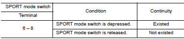
Is the inspection result normal? YES >> INSPECTION END
NO >> Replace SPORT mode switch. Refer to DMS-16, "Removal and Installation".
 Basic inspection
DIAGNOSIS AND REPAIR WORK FLOW
Work Flow
DETAILED FLOW
1.OBTAIN INFORMATION ABOUT SYMPTOM
Interview the customer to obtain as much information as possible about the
conditions and environment un ...
 Symptom diagnosis
THE SPORT MODE INDICATOR LAMP DOES NOT TURN ON
Description
The SPORT mode indicator lamp does not turn ON when the SPORT mode switch is
operated.
Diagnosis Procedure
1.CHECK SPORT MODE INDICATOR ...
Other materials:
Reporting safety defects
For USA
If you believe that your vehicle has a defect
which could cause a crash or could
cause injury or death, you should immediately
inform the National Highway Traffic
Safety Administration (NHTSA) in addition
to notifying NISSAN.
If NHTSA receives similar complaints, it
may open an inv ...
Service data and specifications (sds)
Idle Speed
Condition
Specification
No load* (in P or N position)
650 ± 50 rpm
*: Under the following conditions
A/C switch: OFF
Electric load: OFF (Lights, heater fan & rear window defogger)
Steering wheel: Kept in straight-ahead position
...
Steering gear and linkage
Inspection
BOOT
Check boot for cracks. Replace if any damage is found.
OUTER SOCKET AND INNER SOCKET
Boot
Check boot for cracks, and replace it if a malfunction is
detected.
Gear Housing
Check gear housing for damage and scratches (inner wall). Replace
if there are a ...
