Nissan Rogue (T33) 2021-Present Service Manual: Drive Pinion
Exploded View
 |
Companion flange lock nut |  |
Companion flange |  |
Electro-hydraulic coupling oil seal |
 |
Electro-hydraulic coupling assembly |  |
O-ring |  |
Actuator assembly |
 |
O-ring |  |
Drive pinion oil seal |  |
Drive pinion lock nut |
 |
Pinion front bearing |  |
Gasket |  |
Drain plug |
 |
Filler plug |  |
Coupling oil tank cover |  |
Filler plug |
 |
Gear carrier |  |
Collapsible spacer |  |
Drive pinion adjusting shim |
 |
Pinion rear bearing |  |
Drive pinion |  |
Drive gear |
 |
Differential case |  |
Side bearing |  |
Side bearing adjusting shim |
 |
Side oil seal |  |
Rear cover |  |
Stud bolt |
 |
Pinion mate thrust washer |  |
Pinion mate gear |  |
Side gear thrust washer |
 |
Side gear |  |
Pinion mate shaft |  |
Lock pin |
 |
Outer circumference |  |
Screw hole | ||
 : N┬Ęm (kg-m, in-lb) : N┬Ęm (kg-m, in-lb) |
|||||
 : N┬Ęm (kg-m, ft-lb) : N┬Ęm (kg-m, ft-lb) |
|||||
 : Always replace after every disassembly. : Always replace after every disassembly. |
|||||
 : Select with proper thickness. : Select with proper thickness. |
|||||
 1: Apply gear oil. 1: Apply gear oil. |
|||||
| 2: Apply electro-hydraulic coupling oil (Genuine part). |
|||||
| *: Apply anti-corrosion oil. |
|||||
 : Apply Genuine Silicone RTV or equivalent. Refer to Recommended Chemical Products and Sealants. : Apply Genuine Silicone RTV or equivalent. Refer to Recommended Chemical Products and Sealants. |
|||||
 : Apply Genuine High Strength Thread Locking Sealant or equivalent. Refer to Recommended Chemical Products and Sealants. : Apply Genuine High Strength Thread Locking Sealant or equivalent. Refer to Recommended Chemical Products and Sealants. |
|||||
Disassembly and Assembly
DISASSEMBLY
Remove electro-hydraulic coupling assembly. Refer to Disassembly and Assembly.
Remove differential assembly. Refer to Disassembly and Assembly.
Remove drive pinion oil seal, using oil seal remover (commercial service tool).
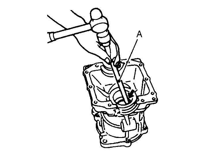
Fit drive pinion socket (A) onto drive pinion spline. Remove drive pinion lock nut, using the pinion nut wrench (B).
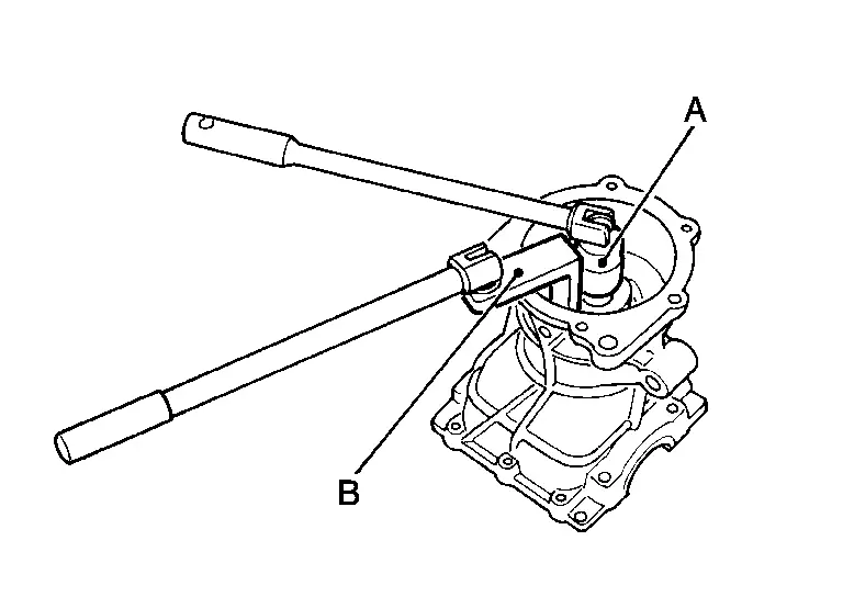
| A | : Drive pinion socket [SST: KV38109300 (NI-53035)] |
| B | : Pinion nut wrench [SST: KV38109900 (NI-53029)] |
 NOTE:
NOTE:
Left-handed screw is used.
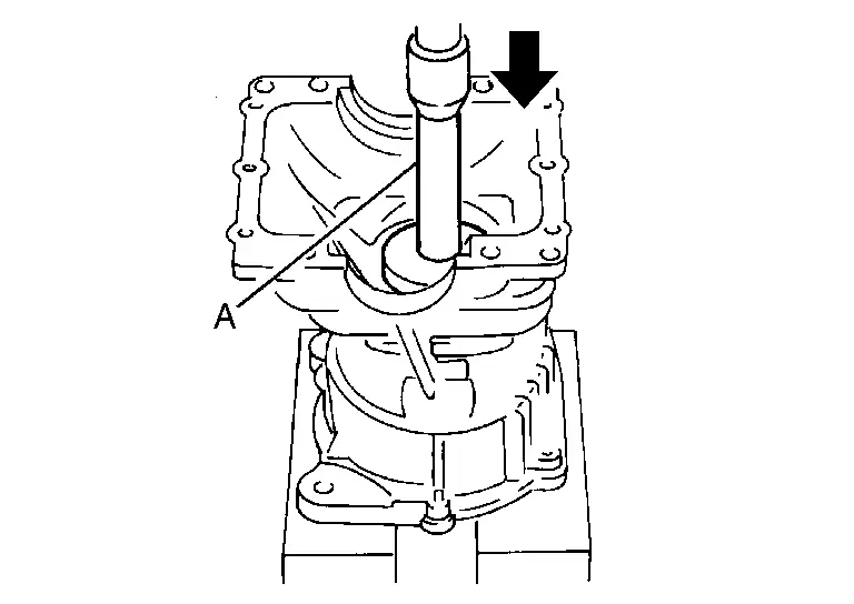
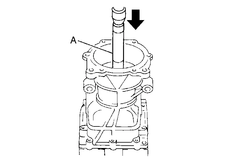
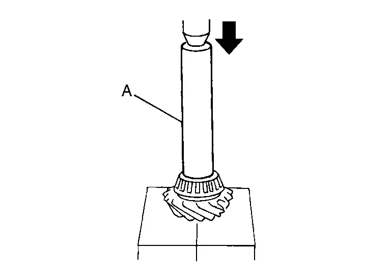
Press drive pinion assembly out of gear carrier.
CAUTION:
Never drop drive pinion assembly.
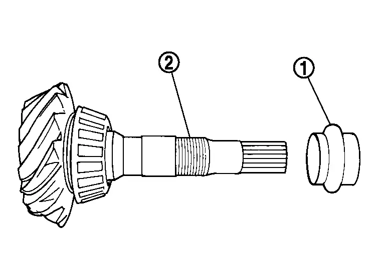
Remove pinion front bearing inner race.
Remove collapsible spacer.
Remove pinion rear bearing inner race from drive pinion, using the separator (A) and the puller (B).
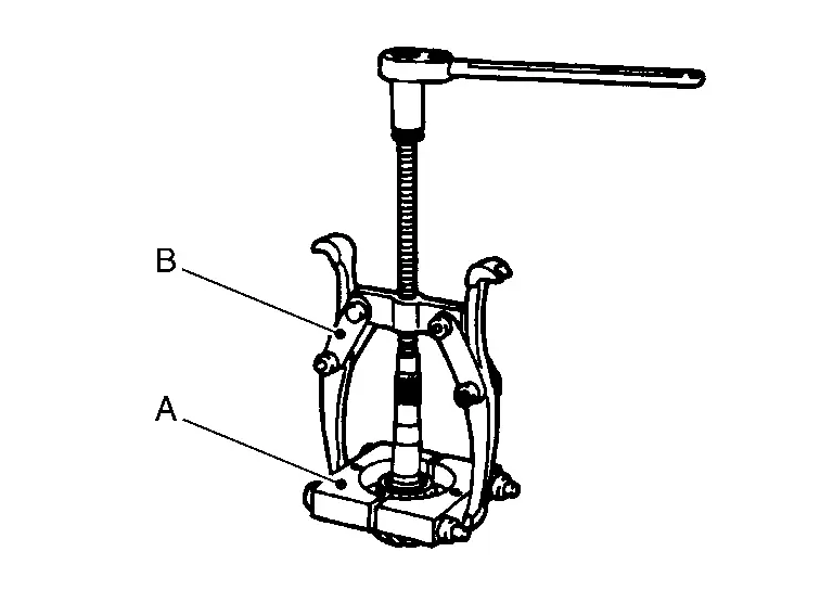
| A | : Separator (commercial service tool) |
| B | : Puller (commercial service tool) |
Using a brass rod or equivalent (A), tap pinion front bearing outer race evenly from the 2 cutouts on gear carrier and remove pinion front bearing outer race.
CAUTION:
Be careful not to damage gear carrier.
Using a brass rod or equivalent (A), tap drive pinion adjusting shim evenly from the 2 cutouts on gear carrier and remove drive pinion adjusting shim and pinion rear bearing outer race.
CAUTION:
Be careful not to damage gear carrier.
Perform inspection after disassembly. Refer to Inspection.
ASSEMBLY
Install a drive pinion adjusting shim of the same thickness as was installed prior to disassembly. Press pinion rear bearing outer race into gear carrier, using the drift (A) [SST: ST33200000 (NI-26082)].
CAUTION:
-
At first, using a hammer, tap bearing outer race until it becomes flush to gear carrier.
-
Never reuse pinion rear bearing outer race.
Press pinion front bearing outer race into gear carrier, using the drift (A) [SST: ST33230000 (NI-25805-01)].
CAUTION:
-
At first, using a hammer, tap bearing outer race until it becomes flush to gear carrier.
-
Never reuse pinion front bearing outer race.
Press pinion rear bearing inner race to drive pinion, using the drift (A) [SST: ST23860000 (ŌĆāŌĆöŌĆā)].
CAUTION:
Never reuse pinion rear bearing inner race.
Check and adjust the tooth contact and back lash of drive gear and drive pinion following the procedure below.Assemble drive pinion into gear carrier.
CAUTION:
-
Never assemble collapsible spacer.
-
Apply gear oil to pinion rear bearing.
CAUTION:
-
Never reuse pinion front bearing inner race.
-
Apply gear oil to pinion front bearing.
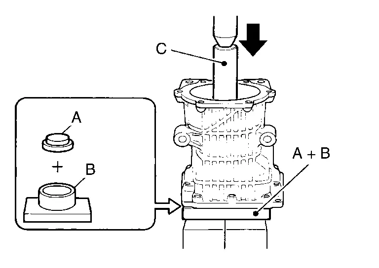
| A | : Drift [SST: KV40100610 (NI-26089)] |
| B | : Press stand [SST: ST38220000 (ŌĆāŌĆöŌĆā)] |
| C | : Drift [SST: ST23860000 (ŌĆāŌĆöŌĆā)] |
NOTE:
Use removed drive pinion lock nut only for the preload measurement.
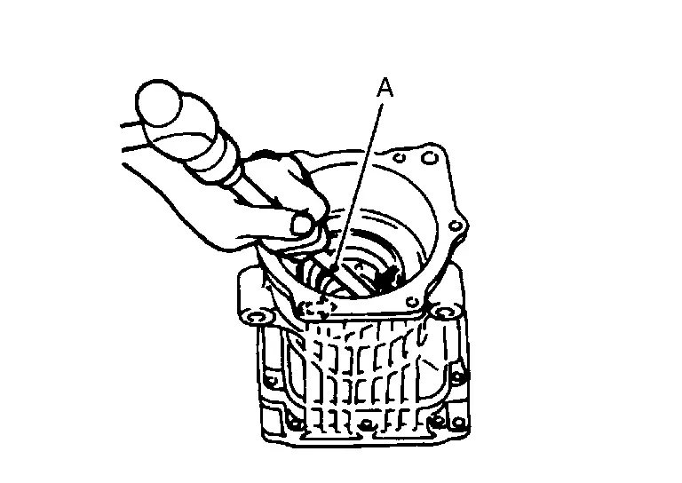
Rotate drive pinion more than 20 times to adjust bearing. Fit the drive pinion socket (A) onto the drive pinion. Using the pinion nut wrench (B), tighten drive pinion lock nut holding drive pinion, while adjusting pinion bearing preload torque using preload gauge (C).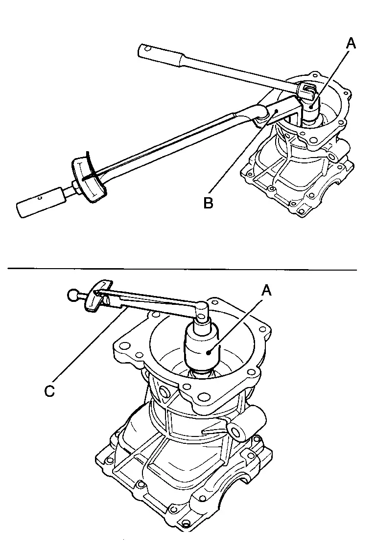
| A | : Drive pinion socket [SST: KV38109300 (NI-53035)] |
| B | : Pinion nut wrench [SST: KV38109900 (NI-53029)] |
| C | : Preload gauge [SST: ST3127S000 (NI-25765-A)] |
| Pinion bearing preload | : Refer to Preload Torque. |
CAUTION:
Drive pinion lock nut is tightened with no collapsible spacer. Be careful not to overtighten it. While measuring the preload, tighten it by 5┬░ to 10┬░.
Install new side bearing adjusting shims (left side: two pieces, right side: one piece) with the same thickness or re-install the old ones to the same mounting position they were in prior to disassembly. Install differential assembly to gear carrier. Refer to Disassembly and Assembly.CAUTION:
Apply differential gear oil to the side bearings.
Check and adjust tooth contact, drive gear to drive pinion backlash. Refer to Adjustment. Remove differential assembly. Remove drive pinion assembly from gear carrier Remove drive pinion nut and press drive pinion assembly out of gear carrier. Remove pinion front bearing inner race.Assemble collapsible spacer to drive pinion .
CAUTION:
-
Be careful of the mounting direction of collapsible spacer.
-
Never reuse collapsible spacer.
Assemble drive pinion into gear carrier.
CAUTION:
Apply gear oil to pinion rear bearing.
Assemble pinion front bearing inner race to drive pinion assembly.
CAUTION:
-
Never reuse pinion front bearing inner race.
-
Apply gear oil to pinion front bearing.
Using the drifts (A and C) and press stand (B), press pinion front bearing inner race to drive pinion as far as drive pinion lock nut can be tightened.
| A | : Drift [SST: KV40100610 (NI-26089)] |
| B | : Press stand [SST: ST38220000 (ŌĆāŌĆöŌĆā)] |
| C | : Drift [SST: ST23860000 (ŌĆāŌĆöŌĆā)] |
Apply anti-corrosion oil to the thread and seat of drive pinion lock nut, and temporarily tighten drive pinion lock nut to drive pinion.
CAUTION:
Never reuse drive pinion lock nut.
Fit the drive pinion socket (A) onto the drive pinion. While holding drive pinion, tighten drive pinion lock nut within the limits of specified torque so as to keep the pinion bearing preload within a standard values, using the pinion nut wrench (B) and the preload gauge (C).
| A | : Drive pinion socket [SST: KV38109300 (NI-53035)] |
| B | : Pinion nut wrench [SST: KV38109900 (NI-53029)] |
| C | : Preload gauge [SST: ST3127S000 (NI-25765-A)] |
| Drive pinion lock nut tightening torque | : Refer to Exploded View. |
| Pinion bearing preload | : Refer to Preload Torque. |
CAUTION:
-
Adjust the lower limit of the drive pinion lock nut tightening torque first.
-
If the preload torque exceeds the specified value, replace collapsible spacer and tighten it again to adjust. Never loose n drive pinion lock nut to adjust the preload torque.
-
After adjustment, rotate drive pinion back and forth 2 to 3 times to check for unusual noise, rotation malfunction, and other malfunctions.
Install differential assembly. Refer to Disassembly and Assembly.
CAUTION:
Never install rear cover at this timing.
Check and adjust drive gear runout, tooth contact, and drive gear to drive pinion backlash. Refer to Adjustment.
Remove dummy cover set, then install rear cover, and side oil seal. Refer to Disassembly and Assembly.
Check total preload torque. Refer to Adjustment.
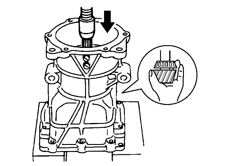
Using the drift (A) (commercial service tool), install drive pinion oil seal within the dimension (D) shown as follows.
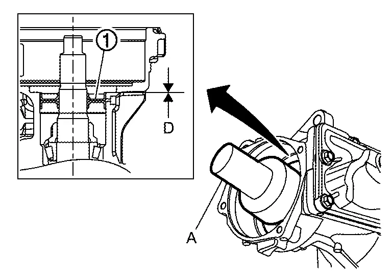
| D | : 0 ┬▒0.4 mm (0 ┬▒0.016 in) |
CAUTION:
-
Never reuse oil seal.
-
When installing, never incline oil seal.
-
Check that the oil seal lip is filled up with grease.
-
Apply gear oil lightly and evenly onto the outer circumference of oil seal.
Install electro-hydraulic coupling assembly. Refer to Disassembly and Assembly.
Inspection
INSPECTION AFTER DISASSEMBLY
Drive Gear and Drive Pinion
-
Clean up the disassembled parts.
-
If the gear teeth never mesh or line-up correctly, determine the cause and adjust or replace as necessary.
-
If the gears are worn, cracked, damaged, pitted or chipped (by friction) noticeably, replace with new drive gear and drive pinion as a set.
Bearing
-
Clean up the disassembled parts.
-
If any chipped (by friction), pitted, worn, rusted or scratched marks, or unusual noise from the bearing is observed, replace as a bearing assembly (as a new set).
Oil Seal
-
Whenever disassembled, replace.
-
If wear, deterioration of adherence (sealing force lips), or damage is detected on the lips, replace them.
Other materials:
B24a4-11 Intake Sensor
DTC Description
DTC DETECTION LOGIC DTC No.
CONSULT screen terms
(Trouble diagnosis content) DTC detection condition
B24A4-11
INTAKE SENSOR
(Intake sensor)
Diagnosis condition
Ignition switch ON
Signal (Terminal)
Intake sensor signal
Threshold
The intake sensor rec ...
System Description. Component Parts. Drive Mode System
Drive Mode System
Component Parts Location
No. Component Function
1.
Drive mode select switch
Refer to Drive Mode Select Switch.
2.
Chassis control module
Chassis control module controls the drive mode select system.
Refer to Component Parts Location (without ProPILOT Assi ...
Precaution. Precautions
Precaution for Supplemental Restraint System (SRS) "AIR BAG" and "SEAT BELT PRE-TENSIONER"
The Supplemental Restraint System such as ŌĆ£AIR BAGŌĆØ and ŌĆ£SEAT BELT
PRE-TENSIONERŌĆØ, used along with a front seat belt, helps to reduce the
risk or severity of injury to the driver and front passeng ...