Nissan Rogue Service Manual: Diagnosis system (combination meter)
Description
COMBINATION METER SELF-DIAGNOSIS MODE
The following meter functions can be checked during Combination Meter Self-Diagnosis Mode:
- Pointer sweep of speedometer, tachometer and gauges.
- Illumination of all LCD segments and color patterns for meter displays.
- Illumination of all lamps/LEDs that are controlled by the combination meter (regardless of switch status).
STARTING COMBINATION METER SELF-DIAGNOSIS MODE
NOTE:
- Check combination meter power supply and ground circuits if self-diagnosis mode does not start. Refer to MWI-59, "COMBINATION METER : Diagnosis Procedure". Replace combination meter if power supply and ground circuits are found to be normal and self-diagnosis mode does not start. Refer to MWI-82, "Removal and Installation".
- Combination meter self-diagnosis mode will function with the ignition switch in ON. Combination meter selfdiagnosis mode will exit upon turning the ignition switch to OFF.
How to Initiate Self-Diagnosis Mode
- Turn ignition switch OFF.
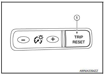
- While pressing the trip reset switch (1), turn ignition switch ON.
- Keep the trip reset switch for 1 seconds or more.
- Press the trip reset switch at least 3 times. (Within 7 seconds after the ignition switch is turned ON.)
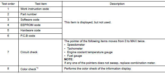
- ŌĆ£Work instruction codeŌĆØ is indicated in the top portion of information display and self-diagnosis is started.
- The mode switches in the order shown below each time the trip
reset switch is pressed.
NOTE: If the trip reset switch is not operated for 20 seconds or more, the self-diagnosis mode is automatically cancelled.
NOTE: When the trip reset switch is pressed during the indication of Test order ŌĆ£10,ŌĆØ test item returns to Test order ŌĆ£2.ŌĆØ *1: Color Check
- Blue
- Red
- Pink
- Green
- Light blue
- Yellow
- White
- White
- Black
- Light blue
- Black
- Pink
- Black
- Blue
- Black
- Dark blue
- White
- Blue
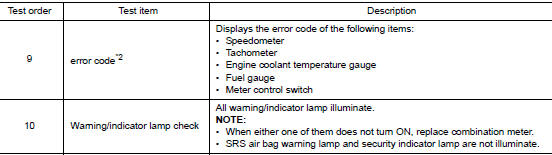
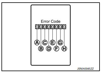
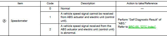
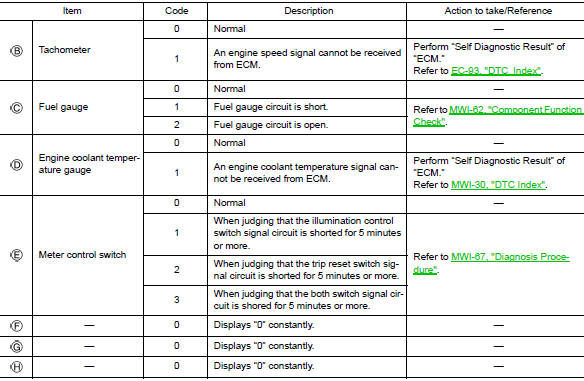
*2: Error Code
How to Reset Error Code
Error codes stored in combination meter can be reset by following the instructions below:
- Turn ignition switch OFF.
- While pressing the trip reset switch, turn ignition switch ON.
- Keep the trip reset switch for 1 seconds or more.
- Press the trip reset switch at least 3 times. (Within 7 seconds after the ignition switch is turned ON.)
- Turn ignition switch OFF.
- Perform self-diagnosis and check that the error codes are reset.
CONSULT Function (METER/M&A)
APPLICATION ITEMS
CONSULT can display each diagnostic item using the diagnostic test modes shown.
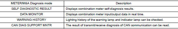
SELF DIAG RESULT
Refer to MWI-30, "DTC Index".
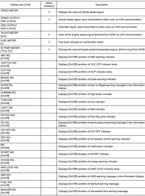
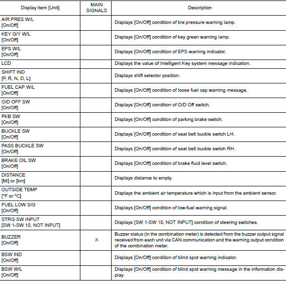
DATA MONITOR
Display Item List
SPECIAL FUNCTION
Special menu

W/L ON HISTORY
- ŌĆ£W/L ON HISTORYŌĆØ indicates the ŌĆ£TIMEŌĆØ when the warning/ indicator lamp is turned on.
- The ŌĆ£TIMEŌĆØ above is:
- 0: The condition that the warning/indicator lamp has been turned on 1 or more times after starting the engine and waiting for 30 seconds.
- 1 - 39: The number of times the engine was restarted after the 0 condition.
- NO W/L ON HISTORY: No warning/indicator lamp history is stored.
NOTE:
- W/L ON HISTORY is not stored for approximately 30 seconds after the engine starts.
- Brake warning lamp does not store any history when the parking brake is applied or the brake fluid level gets low.
 Operation
Switch Name and Function
STEERING SWITCH
No.
Switch name
Operation
Description
1
Enter/Up/Down switch
Press
The information display settings can be changed.
...

Other materials:
P1078 EVT control position sensor
DTC Description
DTC DETECTION LOGIC
DTC No.
CONSULT screen terms
(Trouble diagnosis content)
DTC detecting condition
P1078
EXH TIM SEN/CIRC-B1
(EXH TIM SEN/CIRC-B1)
An excessively high or low voltage from the sensor is sent to ECM.
POSSIBLE CAUSE
H ...
System
System Description
SYSTEM DIAGRAM
OPERATION DESCRIPTION
When rear window defogger switch is turned ON while ignition
switch is ON, the rear window defogger
switch transmits rear window defogger switch signal to BCM.
BCM turns rear window defogger relay ON when rear windo ...
P0327, P0328 KS
DTC Description
DTC DETECTION LOGIC
DTC No.
CONSULT screen terms
(Trouble diagnosis content)
DTC detecting condition
P0327
KNOCK SEN/CIRC-B1
(Knock sensor 1 circuit low bank 1 or single
sensor)
An excessively low voltage from the knock sensor is sent to ECM.
...
