Nissan Rogue Service Manual: System
System Description
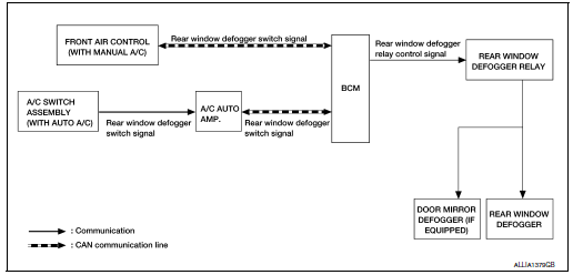
SYSTEM DIAGRAM
OPERATION DESCRIPTION
- When rear window defogger switch is turned ON while ignition switch is ON, the rear window defogger switch transmits rear window defogger switch signal to BCM.
- BCM turns rear window defogger relay ON when rear window defogger switch signal is received.
- Rear window defogger and door mirror defogger (with door mirror defogger) are supplied with power and operate when rear window defogger relay turns ON.
- Rear window defogger ON is displayed when front air control (manual A/C) or A/C switch (auto A/C) receives signals.
TIMER FUNCTION
- BCM turns rear window defogger relay ON for approximately 15 minutes when rear window defogger switch is turned ON while ignition switch is ON. It makes rear window defogger and door mirror defogger (with door mirror defogger) operate.
- Timer is canceled after pressing rear window defogger switch again during timer operation. Then BCM turns rear window defogger relay OFF. The same reaction also occurs during timer operation, if the ignition switch is turned OFF.
INPUT/OUTPUT SIGNAL CHART
|
Switch |
Input signal to BCM |
BCM function |
Actuato |
| Rear window defogger switch | Defogger switch signal | Rear window defogger and door mirror defogger* control | Rear window defogger Door mirror defogger * |
*: With door mirror defogger
 Component parts
Component Parts Location
A/C switch (auto A/C)
Front air control (manual A/C)
No.
Component
Description
1
Rear window defogger connector
(Rear win ...
 Diagnosis system (BCM) (with intelligent key system)
COMMON ITEM
COMMON ITEM : CONSULT Function (BCM - COMMON ITEM)
APPLICATION ITEM
CONSULT performs the following functions via CAN communication with BCM.
Direct Diagnostic Mode
De ...
Other materials:
Diagnosis system (TCM)
DIAGNOSIS DESCRIPTION
DIAGNOSIS DESCRIPTION : 1 Trip Detection Diagnosis and 2 Trip Detection
Diagnosis
NOTE:
“Start the engine and turn OFF the ignition switch after warm-up.” This is
defined as 1 trip.
1 TRIP DETECTION DIAGNOSIS
When initial malfunction is detected, TCM memorizes DTC. ...
Preparation
Special Service Tool
The actual shapes of the tools may differ from those illustrated here.
Tool number
(TechMate No.)
Tool name
Description
—
(J-39570)
Chassis Ear
Locating the noise
—
(J-50397)
NISSAN Squeak and Rattle Kit
...
Precaution
Precaution for supplemental restraint system (srs) "air bag" and "seat
belt
pre-tensioner"
The Supplemental Restraint System such as “AIR BAG” and “SEAT BELT PRE-TENSIONER”,
used along
with a front seat belt, helps to reduce the risk or severity of injury to the
...
