Nissan Rogue Service Manual: P0327, P0328 KS
DTC Description
DTC DETECTION LOGIC
| DTC No. | CONSULT screen terms (Trouble diagnosis content) | DTC detecting condition |
| P0327 | KNOCK SEN/CIRC-B1 (Knock sensor 1 circuit low bank 1 or single sensor) | An excessively low voltage from the knock sensor is sent to ECM. |
| P0328 | KNOCK SEN/CIRC-B1 (Knock sensor 1 circuit high bank 1 or single sensor) | An excessively high voltage from the knock sensor is sent to ECM |
POSSIBLE CAUSE
- Harness or connectors (Knock sensor circuit is open or shorted.)
- Knock sensor
FAIL-SAFE
Not applicable
DTC CONFIRMATION PROCEDURE
1.PRECONDITIONING
If DTC Confirmation Procedure has been previously conducted, always perform the following procedure before conducting the next test.
- Turn ignition switch OFF and wait at least 10 seconds.
- Turn ignition switch ON.
- Turn ignition switch OFF and wait at least 10 seconds.
TESTING CONDITION: Before performing the following procedure, confirm that battery voltage is more than 10 V at idle.
>> GO TO 2.
2.PERFORM DTC CONFIRMATION PROCEDURE
- Start engine and run it for at least 5 seconds at idle speed.
- Check 1st trip DTC.
Is 1st trip DTC detected? YES >> Proceed to EC-293, "Diagnosis Procedure".
NO >> INSPECTION END
Diagnosis Procedure
1.CHECK KNOCK SENSOR GROUND CIRCUIT
- Turn ignition switch OFF.
- Disconnect knock sensor harness connector.
- Disconnect ECM harness connector.
- Check the continuity between knock sensor harness connector and ECM harness connector.
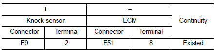
- Also check harness for short to power.
Is the inspection result normal? YES >> GO TO 2.
NO >> Repair or replace error-detected parts.
2.CHECK KNOCK SENSOR INPUT SIGNAL CIRCUIT
- Check the continuity between knock sensor harness connector and ECM harness connector.
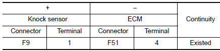
- Also check harness for short to ground and to power.
Is the inspection result normal? YES >> GO TO 3.
NO >> Repair open circuit or short to ground or short to power in harness or connectors.
3.CHECK KNOCK SENSOR
Check the knock sensor. Refer to EC-294, "Component Inspection".
Is the inspection result normal? YES >> GO TO 4.
NO >> Replace knock sensor. Refer to EM-92, "Exploded View".
4.CHECK INTERMITTENT INCIDENT
Refer to GI-41, "Intermittent Incident".
>> INSPECTION END
Component Inspection
1.CHECK KNOCK SENSOR
- Turn ignition switch OFF.
- Disconnect knock sensor harness connector.
- Check resistance between knock sensor terminals as per the following.
NOTE: It is necessary to use an ohmmeter which can measure more than 10 MΩ.
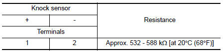
CAUTION: Do not use any knock sensors that have been dropped or physically damaged. Use only new ones. Is the inspection result normal?
YES >> INSPECTION END
NO >> Replace knock sensor. Refer to EM-92, "Exploded View".
 P0300, P0301, P0302, P0303, P0304 misfire
DTC Description
DTC DETECTION LOGIC
When a misfire occurs, engine speed will fluctuate. If the engine speed
fluctuates enough to cause the crankshaft
position (CKP) sensor (POS) signal to vary, E ...
 P0335 CKP sensor (POS)
DTC Description
DTC DETECTION LOGIC
DTC No.
CONSULT screen terms
(Trouble diagnosis content)
DTC detecting conditio
P0335
CKP SEN/CIRCUIT
(Crankshaft position sensor & ...
Other materials:
Child safety
WARNINGDo not allow children to play with the seat
belts. Most seating positions are
equipped with Automatic Locking Retractor
(ALR) mode seat belts. If the seat belt
becomes wrapped around a child’s neck
with the ALR mode activated, the child can
be seriously injured or k ...
Interior room lamp control circuit
Description
Controls each interior room lamp (ground side) by PWM signal.
NOTE:
PWM signal control period is approximately 250 Hz (in the gradual
brightening/dimming).
Component Function Check
CAUTION:
Before performing the diagnosis, check that the following is normal.
Interior ro ...
Sensor power supply2 circuit
Description
ECM supplies a voltage of 5 V to some of the sensors systematically divided
into 2 groups, respectively.
Accordingly, when a short circuit develops in a sensor power source, a
malfunction may occur simultaneously
in the sensors belonging to the same group as the short-circuited ...
