Nissan Rogue Service Manual: Diagnosis and repair workflow
Work Flow
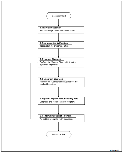
OVERALL SEQUENCE
DETAILED FLOW
1. OBTAIN INFORMATION ABOUT SYMPTOM
Interview the customer to obtain as much information as possible about the conditions and environment under which the malfunction occurred.
>> GO TO 2.
2. CONFIRM THE SYMPTOM
Check the malfunction on the vehicle that the customer describes.
Inspect the relation of the symptoms and the condition when the symptoms occur.
>> GO TO 3.
3. IDENTIFY THE MALFUNCTIONING SYSTEM WITH SYMPTOM DIAGNOSIS
Use Symptom diagnosis from the symptom inspection result in step 2 and then identify where to start performing the diagnosis based on possible causes and symptoms.
>> GO TO 4.
4. PERFORM THE COMPONENT DIAGNOSIS OF THE OF THE APPLICABLE SYSTEM
Perform the diagnosis with Component diagnosis of the applicable system.
>> GO TO 5.
5. REPAIR OR REPLACE THE MALFUNCTIONING PARTS
Repair or replace the specified malfunctioning parts.
>> GO TO 6.
6. FINAL CHECK
Check that malfunctions are not reproduced when obtaining the malfunction information from the customer, referring to the symptom inspection result in step 2.
Are the malfunctions corrected? YES >> Inspection End.
NO >> GO TO 3.
 Basic inspection
...
 Inspection and adjustment
ADDITIONAL SERVICE WHEN REMOVING BATTERY NEGATIVE TERMINAL
ADDITIONAL SERVICE WHEN REMOVING BATTERY NEGATIVE TERMINAL : Description
If any of the following work has been done Initial setting is nece ...
Other materials:
Tire pressure sensor
Exploded View
Tire pressure sensor
O-ring
Valve stem nut
Valve core
Valve cap
Valve stem assembly
: Parts that are replaced as a
set when the tire is replaced.
Removal and Installation
REMOVAL
Remove wheel and tire using power tool.
Remove v ...
Removal and installation
FRONT CAMERA
Exploded View
Front grille
Front camera
Removal and Installation
REMOVAL
Remove the front grille. Refer to EXT-23, "Removal and
Installation".
Remove screws and front camera.
INSTALLATION
Installation is in the reverse order of re ...
ID registration cannot be completed
Description
The ID of the tire pressure sensor installed in each wheel cannot be
registered in the tire pressure monitoring
system. Inspect the tire pressure sensor or the tire pressure monitoring system
circuit.
Diagnosis Procedure
1.CHECK TIRE PRESSURE SENSOR ACTIVATION TOOL
Check tire pr ...
