Nissan Rogue Service Manual: P0138 HO2S2
DTC Description
DTC DETECTION LOGIC
The heated oxygen sensor 2 has a much longer switching time between rich and lean than the air fuel ratio (A/ F) sensor 1. The oxygen storage capacity of the three way catalyst (manifold) causes the longer switching time.
MALFUNCTION A
To judge the malfunctions of heated oxygen sensor 2, ECM monitors whether the voltage is unusually high during the various driving condition such as fuel-cut.
MALFUNCTION B
To judge the malfunctions of heated oxygen sensor 2, ECM monitors whether the minimum voltage of sensor is sufficiently low during the various driving condition such as fuel-cut.
| DTC No. | CONSULT screen terms (Trouble diagnosis content) | DTC detecting con | |
| P0138 | HO2S2 (B1) (O2 sensor circuit high voltage bank 1 sensor 2) | A | An excessively high voltage from the sensor is sent to ECM |
| B | The minimum voltage from the sensor is not reached to the specified voltage. | ||
POSSIBLE CAUSE
DTC P0138 - A
- Harness or connectors (The sensor circuit is open or shorted.)
- Heated oxygen sensor 2
DTC P0138 - B
- Harness or connectors (The sensor circuit is open or shorted.)
- Heated oxygen sensor 2
- Fuel pressure
- Fuel injector
FAIL-SAFE
Not applicable
DTC CONFIRMATION PROCEDURE
1.PRECONDITIONING
If DTC Confirmation Procedure has been previously conducted, always perform the following procedure before conducting the next test.
- Turn ignition switch OFF and wait at least 10 seconds.
- Turn ignition switch ON.
- Turn ignition switch OFF and wait at least 10 seconds.
>> GO TO 2.
2.PERFORM DTC CONFIRMATION PROCEDURE FOR MALFUNCTION A
- Start engine and warm it up to normal operating temperature.
- Turn ignition switch OFF and wait at least 10 seconds.
- Start engine and keep the engine speed between 3,500 and 4,000 rpm for at least 1 minute under no load.
- Let engine idle for 2 minutes.
- Check 1st trip DTC.
Is 1st trip DTC detected? YES >> Proceed to EC-244, "Diagnosis Procedure".
NO-1 >> With CONSULT: GO TO 3.
NO-2 >> Without CONSULT: GO TO 5.
3.PERFORM DTC CONFIRMATION PROCEDURE FOR MALFUNCTION B
NOTE: For better results, perform “DTC WORK SUPPORT” at a temperature of 0 to 30°C (32 to 86°F).
- Turn ignition switch ON and select “DATA MONITOR” mode of “ENGINE” using CONSULT.
- Start engine and warm it up to normal operating temperature.
- Turn ignition switch OFF and wait at least 10 seconds.
- Start engine and keep the engine speed between 3,500 and 4,000 rpm for at least 1 minute under no load.
- Let engine idle for 1 minute.
- Make sure that “COOLAN TEMP/S” indication is more than 70°C (158°F).
If not, warm up engine and go to next step when “COOLAN TEMP/S” indication reaches 70°C (158°F).
- Open engine hood.
- Select “HO2S2 (B1) P1146” of “HO2S2” in “DTC WORK SUPPORT” mode of “ENGINE” using CONSULT.
- Follow the instruction of CONSULT.
NOTE: It will take at most 10 minutes until “COMPLETED” is displayed.
- Touch “SELF-DIAG RESULT”.
Which is displayed on CONSULT
OK >> INSPECTION END
NG >> Proceed to EC-244, "Diagnosis Procedure".
CAN NOT BE DIAGNOSED>>GO TO 4.
4.PERFORM DTC CONFIRMATION PROCEDURE FOR MALFUNCTION B AGAIN
- Turn ignition switch OFF and leave the vehicle in a cool place (soak the vehicle).
- Perform DTC confirmation procedure again.
>> GO TO 3.
5.PERFORM COMPONENT FUNCTION CHECK-1
 Without CONSULT
- Start engine and warm it up to normal operating temperature.
- Turn ignition switch OFF and wait at least 10 seconds.
- Start engine and keep the engine speed between 3,500 and 4,000 rpm for at least 1 minute under no load.
- Let engine idle for 1 minute.
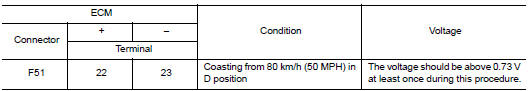
- Check the voltage between ECM harness connector and ground as per the following condition.
Is the inspection result normal? YES >> INSPECTION END
NO >> GO TO 6.
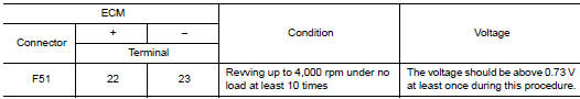
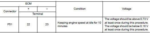
6.PERFORM COMPONENT FUNCTION CHECK-2
Check the voltage between ECM harness connector and ground as per the following condition.
Is the inspection result normal? YES >> INSPECTION END
NO >> GO TO 7.
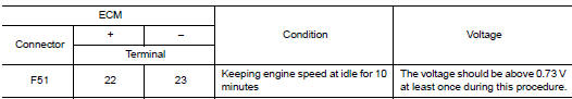
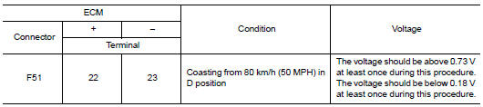
7.PERFORM COMPONENT FUNCTION CHECK-3
Check the voltage between ECM harness connector and ground as per the following condition.
Is the inspection result normal? YES >> INSPECTION END
NO >> Proceed to EC-244, "Diagnosis Procedure".
Diagnosis Procedure
1.INSPECTION START
Confirm the detected malfunction (A or B). Refer to EC-242, "DTC Description".
Which malfunction is detected? A >>GO TO 2.
B >>GO TO 7.
2.CHECK HO2S2 CONNECTOR FOR WATER
- Turn ignition switch OFF.
- Disconnect heated oxygen sensor 2 harness connector.
- Check connectors for water.
Water should not exist.
Is the inspection result normal? YES >> GO TO 3.
NO >> Repair or replace error-detected parts.
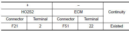
3.CHECK HO2S2 GROUND CIRCUIT
- Disconnect ECM harness connector.
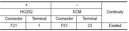
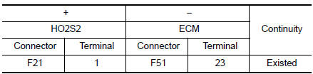
- Check the continuity between HO2S2 harness connector and ECM harness connector.
- Also check harness for short to power.
Is the inspection result normal? YES >> GO TO 4.
NO >> Repair or replace error-detected parts.
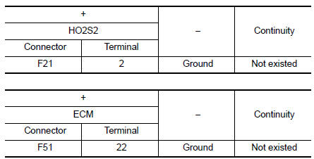
4.CHECK HO2S2 INPUT SIGNAL CIRCUIT
- Check the continuity between HO2S2 harness connector and ECM harness connector.

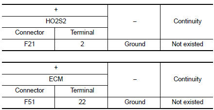
- Check the continuity between HO2S2 harness connector and ground, or ECM harness connector and ground.
- Also check harness for short to power.
Is the inspection result normal? YES >> GO TO 5.
NO >> Repair or replace error-detected parts.
5.CHECK HEATED OXYGEN SENSOR 2
Check the heated oxygen sensor 2. Refer to EC-247, "Component Inspection".
Is the inspection result normal? YES >> Check intermittent incident. Refer to GI-41, "Intermittent Incident".
NO >> GO TO 6.
6.REPLACE HEATED OXYGEN SENSOR 2
Replace heated oxygen sensor 2. Refer to EX-5, "Exploded View".
CAUTION:
- Discard any sensor which has been dropped from a height of more than 0.5 m (19.7 in) onto a hard surface such as a concrete floor; use a new one.
- Before installing new sensor, clean exhaust system threads using Oxygen Sensor Thread Cleaner [commercial service tool (J-43897-18 or J43897-12)] and approved Anti-seize Lubricant (commercial service tool).
>> INSPECTION END
7.CLEAR THE MIXTURE RATIO SELF-LEARNING VALUE
- Clear the mixture ratio self-learning value. Refer to EC-143, "Work Procedure".
- Run engine for at least 10 minutes at idle speed.
Is the 1st trip DTC P0172 detected? Is it difficult to start engine? YES >> Perform trouble diagnosis for DTC P0172. Refer to EC-265, "DTC Description".
NO >> GO TO 8.
8.CHECK HO2S2 GROUND CIRCUIT
- Turn ignition switch OFF.
- Disconnect heated oxygen sensor 2 harness connector.
- Disconnect ECM harness connector.
- Check the continuity between HO2S2 harness connector and ECM harness connector.
- Also check harness for short to ground and to power.
Is the inspection result normal? YES >> GO TO 9.
NO >> Repair or replace error-detected parts.
9.CHECK HO2S2 INPUT SIGNAL CIRCUIT
- Check the continuity between HO2S2 harness connector and ECM harness connector.
- Check the continuity between HO2S2 harness connector and ground, or ECM harness connector and ground.
- Also check harness for short to power.
Is the inspection result normal? YES >> GO TO 10.
NO >> Repair open circuit or short to ground or short to power in harness or connectors.
10.CHECK HEATED OXYGEN SENSOR 2
Check the heated oxygen sensor 2. Refer to EC-247, "Component Inspection".
Is the inspection result normal? YES >> Check intermittent incident. Refer to GI-41, "Intermittent Incident".
NO >> GO TO 11.
11.REPLACE HEATED OXYGEN SENSOR 2
Replace heated oxygen sensor 2. Refer to EX-5, "Exploded View".
CAUTION:
- Discard any sensor which has been dropped from a height of more than 0.5 m (19.7 in) onto a hard surface such as a concrete floor; use a new one.
- Before installing new sensor, clean exhaust system threads using Oxygen Sensor Thread Cleaner [commercial service tool (J-43897-18 or J43897-12)] and approved Anti-seize Lubricant (commercial service tool).
>> INSPECTION END
Component Inspection
1.INSPECTION START
Do you have CONSULT? Do you have CONSULT? YES >> GO TO 2.
NO >> GO TO 3.
2.CHECK HEATED OXYGEN SENSOR 2
 With CONSULT
- Turn ignition switch ON and select “DATA MONITOR” mode of “ENGINE” using CONSULT.
- Start engine and warm it up to normal operating temperature.
- Turn ignition switch OFF and wait at least 10 seconds.
- Start engine and keep the engine speed between 3,500 and 4,000 rpm for at least 1 minute under no load.
- Let engine idle for 1 minute.
- Select “FUEL INJECTION” in “ACTIVE TEST” mode of “ENGINE” using CONSULT, and select “HO2S2 (B1)” as the monitor item with CONSULT.
- Check “HO2S2 (B1)” at idle speed when adjusting “FUEL INJECTION” to ± 25%.
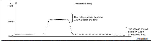
“HO2S2 (B1)” should be above 0.73 V at least once when the “FUEL INJECTION” is + 25%.
“HO2S2 (B1)” should be below 0.18 V at least once when the “FUEL INJECTION” is − 25%.
Is the inspection result normal? YES >> INSPECTION END
NO >> GO TO 6.
3.CHECK HEATED OXYGEN SENSOR 2-1
 Without CONSULT
- Start engine and warm it up to normal operating temperature.
- Turn ignition switch OFF and wait at least 10 seconds.
- Start engine and keep the engine speed between 3,500 and 4,000 rpm for at least 1 minute under no load.
- Let engine idle for 1 minute.
- Check the voltage between ECM harness connector and ground as per the following condition.
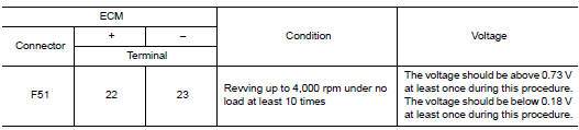
Is the inspection result normal? YES >> INSPECTION END
NO >> GO TO 4.
4.CHECK HEATED OXYGEN SENSOR 2-2
Check the voltage between ECM harness connector and ground as per the following condition.
Is the inspection result normal?
YES >> INSPECTION END
NO >> GO TO 5.
5.CHECK HEATED OXYGEN SENSOR 2-3
Check the voltage between ECM harness connector and ground as per the following condition.
Is the inspection result normal? YES >> INSPECTION END
NO >> GO TO 6.
6.REPLACE HEATED OXYGEN SENSOR 2
Replace heated oxygen sensor 2. Refer to EX-5, "Exploded View".
CAUTION:
- Discard any sensor which has been dropped from a height of more than 0.5 m (19.7 in) onto a hard surface such as a concrete floor; use a new one.
- Before installing new sensor, clean exhaust system threads using Oxygen Sensor Thread Cleaner [commercial service tool (J-43897-18 or J43897-12)] and approved Anti-seize Lubricant (commercial service tool).
>> INSPECTION END
 P0137 HO2S2
DTC Description
DTC DETECTION LOGIC
The heated oxygen sensor 2 has a much longer switching time
between rich and lean than the air fuel ratio (A/F) sensor 1. The oxygen
storage capacity of the thr ...
 P0139 HO2S2
DTC Description
DTC DETECTION LOGIC
The heated oxygen sensor 2 has a much longer switching time
between rich and lean than the air fuel ratio (A/F) sensor 1. The oxygen
storage capacity of the thr ...
Other materials:
P0452 EVAP control system pressure sensor
DTC Description
DTC DETECTION LOGIC
DTC No.
CONSULT screen terms
(Trouble diagnosis content)
DTC detecting condition
P0452
EVAP SYS PRES SEN
(Evaporative emission system pressure
sensor/switch low)
An excessively low voltage from the sensor is sent to ECM.
...
Rear window defogger power supply and ground circuit
Description
Heats the heating wire with the power supply from the rear window defogger
relay to prevent the rear window
from fogging up.
Component Function Check
1. CHECK REAR WINDOW DEFOGGER
Check that the heating wire of rear window defogger is heated when turning
the rear window defogger ...
Unit disassembly and assembly
TORQUE CONVERTER AND CONVERTER HOUSING OIL SEAL
Exploded View
Torque converter
O-ring
Converter housing oil seal
Transaxle assembly
: Always replace after every
disassembly.
: Apply CVT fluid
Disassembly
Remove transaxle assembly. Refer to TM-220, "Removal and Instal ...
