Nissan Rogue Service Manual: CVT position
Inspection
- Turn ON the ignition switch with the shift selector at the “P” position.
- Press the shift selector button with the brake pedal depressed, and confirm that the shift selector can be moved to positions other than “P”. Also confirm that movement is not allowed from the “P” position to other position without depressing the brake pedal.
- Move the shift selector and check for “excessive effort”, “sticking”, “noise” or “rattle”.
- Confirm that shift selector stops at each position with the feel of engagement when it is moved through all the positions. Check whether or not the actual position the shift selector is in matches the position shown by the transaxle body.
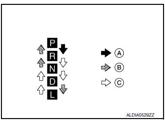
- Make sure that the shift selector is moved to all the shift positions in the manner shown.
- (A): Press shift selector button to operate shift selector, while depressing the brake pedal.
- (B): Press shift selector button to operate shift selector.
- (C): Shift selector can be operated without pressing the shift selector button.
- When the shift selector button is pressed without applying forward/ backward force to the shift selector at “P”, “R”, “N”, “D” or "L" positions, there should be no “sticking” on the shift selector button operation.
- Check that the back-up lamps do not illuminate when the shift selector is in the “P” position.
CAUTION: Check the lighting without pressing shift button.
- Check that the engine can be started with the shift selector in the “P” and “N” positions only.
- Check that the transaxle is locked completely when the shift selector is in the “P” position.
- The relationship between shift selector, engine starting ability, and shift position indicator lighting should satisfy the conditions of the following table.
| Shift selector position | Load direction to the shift selector | Applied load to the shift selector | Engine starting ability | Shift position indicator lighting |
| P | P (over stroke) ‚Üê P ‚Üí R | 29.4 N (3.00 kg, 6.61 lb) | Start | P indicator shall be illuminated |
| R | P ‚Üê R | Not start | R indicator shall be illuminated | |
| N | R ← N | — | N indicator shall be illuminated | |
| — | — | Start | ||
| D | — | — | Not start | D indicator shall be illuminated |
| L | — | — | Not start | L indicator shall be illuminated |
Adjustment
- Move the selector lever to the “P” position.
CAUTION: Rotate the wheels at least a quarter turn and be certain the Park position mechanism is fully engaged.
- Loosen nut (A) and set manual lever (1) to the “P” position.
CAUTION: Do not apply force to the manual lever.
- Hold the control cable (2) and push it to direction of the arrow with a specified force.
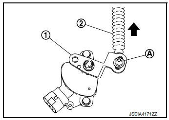
Specified force : 9.8 N (1.0 kg, 2.2 lb)
- Temporarily tighten the nut with the control cable loose.
- Tighten the nut to the specified torque. Refer to TM-197, "Exploded View".
CAUTION: Hold the manual lever securely in the "P" position when tightening control cable nut.
How to erase permanent DTC
Description
Permanent DTC can be erased by driving each driving pattern.
ECM recognizes each driving pattern; it transmits signals to each control module when the driving is complete.
Each control module erases permanent DTC based on those signals. For details, refer to EC-151, "Description".
 Stall test
Work Procedure
INSPECTION
Check the engine oil level. Replenish if necessary. Refer to LU-7,
"Inspection".
Check for leak of the CVT fluid. Refer to TM-190, "Inspe ...

Other materials:
Supplemental air bag warning light
The supplemental air bag warning light,
displaying in the instrument panel,
monitors
the circuits for the air bag systems, pretensioners
and all related wiring.
When the ignition switch is placed in the ON
position, the supplemental air bag warning light
illuminates for about 7 second ...
Chassis maintenance
EXHAUST SYSTEM
EXHAUST SYSTEM : Inspection
Check exhaust pipes, muffler, and mounting for improper attachment,
leakage, cracks, damage or deterioration.
If anything is found, repair or replace damaged parts.
CVT FLUID
CVT FLUID : Inspection
FLUID LEAKAGE
Check transax ...
Component parts
Component Parts Location
Condenser
Compressor
Refrigerant pressure sensor
Liquid tank
Expansion valve
Evaporator
Component Description
Component
Description
Compressor
Intakes, compresses and discharges refrigerant to circulate
refrigerant ...
