Nissan Rogue Service Manual: Stall test
Work Procedure
INSPECTION
- Check the engine oil level. Replenish if necessary. Refer to LU-7, "Inspection".
- Check for leak of the CVT fluid. Refer to TM-190, "Inspection".
- Drive for about 10 minutes to warm up the vehicle so that the CVT fluid temperature is 50 to 80°C (122 to 176°F).
- Be sure to apply the parking brake and block the tires.
- Start the engine, depress the brake pedal and put the selector lever to the D position.
- While depressing the brake pedal, depress the accelerator pedal gradually.
- Read the stall speed quickly. Then, release your foot from the accelerator pedal quickly.
CAUTION: Do not depress the accelerator pedal for 5 seconds or more during the test.
Stall speed : Refer to TM-226, "Stall Speed".
- Place the selector lever in the N position.
- Cool the CVT fluid.
CAUTION: Run the engine with the idle speed for at least 1 minute.
- Put the selector lever to the R position and perform Step 6 to Step 9 again.
NARROWING-DOWN MALFUNCTIONING PARTS
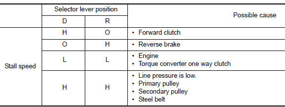
O: Within the stall speed standard value.
H: Stall speed is higher than the standard value.
L: Stall speed is lower than the standard value.
 CVT fluid cooler system
Cleaning
Whenever an automatic transaxle is repaired, overhauled, or replaced, the CVT
fluid cooler mounted in the
radiator must be inspected and cleaned.
Metal debris and friction material, if ...
 CVT position
Inspection
Turn ON the ignition switch with the shift selector at the “P” position.
Press the shift selector button with the brake pedal depressed,
and confirm that the shift select ...
Other materials:
FM radio reception
Range: FM range is normally limited to 25 – 30 mi
(40 – 48 km), with monaural (single channel) FM
having slightly more range than stereo FM. External
influences may sometimes interfere with FM
station reception even if the FM station is within
25 mi (40 km). The strength of the FM signal is ...
Sunshade motor assembly
Removal and Installation
REMOVAL
Remove the headlining. Refer to. INT-30, "Removal and Installation".
Disconnect the harness connector (A) from the sunshade motor
assembly (1).
Remove sunshade motor assembly screws (B).
Remove the sunshade motor assembl ...
Roof rack
Exploded View
Roof rack rear bolt cover
Roof rack front bolt cover
Roof rack
Roof side molding
Back door hinge cover
Metal Clip
Pawl
Removal and Installation
REMOVAL
Release pawls and remove roof rack front and rear cover (1)
using suitable tool (A ...
