Nissan Rogue Service Manual: Chassis maintenance
EXHAUST SYSTEM
EXHAUST SYSTEM : Inspection
Check exhaust pipes, muffler, and mounting for improper attachment, leakage, cracks, damage or deterioration.
- If anything is found, repair or replace damaged parts.
CVT FLUID
CVT FLUID : Inspection
FLUID LEAKAGE
- Check transaxle surrounding area (oil seal and plug etc.)for fluid leakage.
- If anything is found, repair or replace damaged parts and adjust CVT fluid level. Refer to MA-29, "CVT FLUID : Adjustment".
CVT FLUID : Replacement
Recommended fluid and fluid capacity : Refer to TM-226, "General Specification".
CAUTION:
- Always use shop paper. Never use shop cloth.
- Replace a drain plug gasket with new ones at the final stage of the operation when installing.
- Use caution when looking into the drain hole as there is a risk of dripping fluid entering the eye.
- After replacement, always perform CVT fluid leakage check.
- Select “Data Monitor” in “TRANSMISSION” using CONSULT.
- Select “FLUID TEMP” and confirm that the CVT fluid temperature is 40°C (104°F) or less.
- Check that the selector lever is in the “P” position, then completely engage the parking brake.
- Lift up the vehicle.
- Remove the drain plug and drain the CVT fluid from the oil pan. Refer to TM-205, "Exploded View".
- Install the drain plug to oil pan.
CAUTION: Drain plug gasket use the old one.
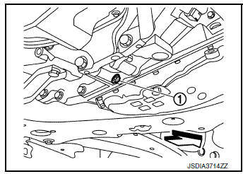
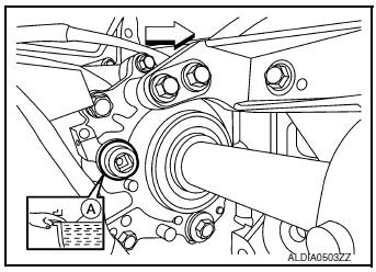
- Remove the overflow plug 1from converter housing.
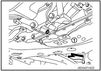
 : Vehicle front
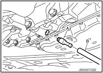
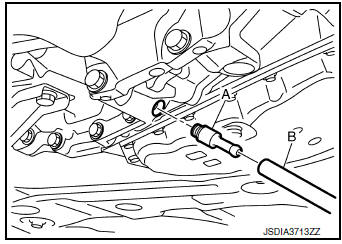
- Install the charging pipe set (KV311039S0) (A) into the overflow
plug hole.
CAUTION: Tighten the charging pipe by hand.
- Install the ATF changer hose (B) to the charging pipe.
CAUTION: Press the ATF changer hose all the way onto the charging pipe until it stops.
- Fill approximately 3 liter (3-1/8 US qt, 2-5/8 lmp qt) of the CVT fluid.
- Remove the ATF changer hose and charging pipe, then install
the overflow plug.
NOTE: Perform this work quickly because CVT fluid leaks.
- Lift down the vehicle.
- Start the engine.
- While depressing the brake pedal, shift the selector lever to the
entire position from “P” to “L”, and shift it
to the “P” position.
NOTE: Hold the lever at each position for 5 seconds.
- Check that the CONSULT “Data Monitor” in “FLUID TEMP” is 35°C (95°F) to 45°C (113°F).
- Stop the engine.
- Lift up the vehicle.
- Remove the drain plug, and then drain CVT fluid from oil pan.
- Repeat steps 8 to 18 (one time).
- Tighten the drain plug to the specified torque. Refer to TM-205, "Exploded View".
- Remove the overflow plug.
- Install the charging pipe set (KV311039S0) into the overflow plug
hole.
CAUTION: Tighten the charging pipe by hand.
- Install the ATF changer hose to the charging pipe.
CAUTION: Press the ATF changer hose all the way onto the charging pipe until it stops.
- Fill approximately 3 liter (3-1/8 US qt, 2-5/8 lmp qt) of the CVT fluid.
- Remove the ATF changer hose and charging pipe, then install the
overflow plug.
NOTE: Perform this work quickly because CVT fluid leaks.
- Lift down the vehicle.
- Start the engine.
- While depressing the brake pedal, shift the selector lever to the
entire position from “P” to “L”, and shift it
to the “P” position.
NOTE: Hold the lever at each position for 5 seconds.
- Check that the CONSULT “Data Monitor” in “FLUID TEMP” is 35°C (95°F) to 45°C (113°F).
- Lift up the vehicle.
- Remove the overflow plug and confirm that the CVT fluid is drained
from the overflow plug hole.
CAUTION: Perform this work with the vehicle idling.
NOTE: If the CVT fluid is not drained, refer to “Adjustment” and refill with the CVT fluid.
- When the flow of CVT fluid slows to a drip, tighten the overflow
plug to the specified torque. Refer to TM-
205, "Exploded View".
CAUTION: Never reuse O-ring.
- Lift down the vehicle.
- Select “Data Monitor” in “TRANSMISSION” using CONSULT.
- Select “CONFORM CVTF DETERIORTN”.
- Select “Erase”.
- Stop the engine.
CVT FLUID : Adjustment
Recommended fluid and fluid capacity : Refer to TM-226, "General Specification".
CAUTION:
- During adjustment of the CVT fluid level, check CONSULT so that the oil temperature may be maintained from 35 to 45°C (95 to 113°F).
- During adjustment of the CVT fluid level, check that the engine speed is maintaining 500 rpm.
- Use caution when looking into the drain hole as there is a risk of dripping fluid entering the eye.
- Check that the selector lever is in the “P” position, then completely engage the parking brake.
- Start the engine.
- Adjust the CVT fluid temperature to be approximately 40°C (104°F).
NOTE: The CVT fluid is largely affected by temperature. Therefore be sure to use CONSULT and check the “FLUID TEMP” under “TRANSMISSION” in “Data Monitor” while adjusting.
- While depressing the brake pedal, shift the selector lever to the
entire position from “P” to “L”, and shift it
to the “P” position.
NOTE: Hold the lever at each position for 5 seconds.
- Lift up the vehicle.
- Check that there is no CVT fluid leakage.
- Remove the overflow plug 1 from converter housing.
 : Vehicle front
- Install the charging pipe set (KV311039S0) (A) into the overflow
plug hole.
CAUTION: Tighten the charging pipe by hand.
- Install the ATF changer hose (B) to the charging pipe.
CAUTION: Press the ATF changer hose all the way onto the charging pipe until it stops.
- Fill approximately 0.5 liter (1/2 US qt, 1/2 lmp qt) of the CVT fluid.
- Remove the ATF changer hose from the charging pipe, and
check that the CVT fluid drains out from the charging pipe. If it
does not drain out, perform charging again.
CAUTION: Perform this work with the vehicle idling.
- When the flow of CVT fluid slows to a drip, remove the charging pipe from the converter housing.
- Tighten the overflow plug to the specified torque. Refer to
TM-205, "Exploded View".
CAUTION: Never reuse O-ring.
- Lift down the vehicle.
- Stop the engine.
TRANSFER OIL
TRANSFER OIL : Inspection
TRANSFER OIL LEAKS
Check that transfer oil is not leaking from transfer assembly or around it.
TRANSFER OIL LEVEL
CAUTION: Do not start engine while checking transfer oil level.
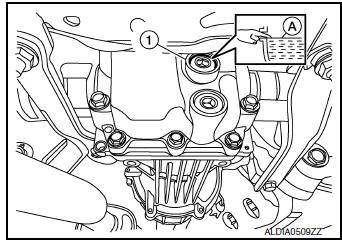
- Remove filler plug (1) and gasket.
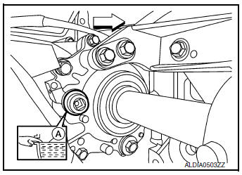
: Vehicle front
- Transfer oil level (A) should be level with bottom of filler plug hole. Add transfer oil if necessary. Refer to MA-11, "Fluids and Lubricants".
- Set a new gasket onto filler plug, and install it in the transfer and tighten to specified torque. Refer to DLN-89, "Exploded View".
CAUTION: Do not reuse gasket.
TRANSFER OIL : Draining
CAUTION: Do not start engine while working.
- Run the vehicle to warm up the transfer unit sufficiently.
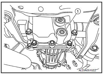
- Stop the engine and remove drain plug (1) and gasket and drain the transfer oil.
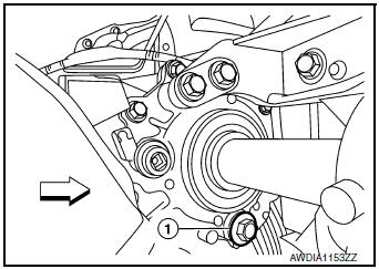
: front
- Set a new gasket onto drain plug, and install it in the transfer
and tighten to specified torque. Refer to DLN-89, "Exploded
View".
CAUTION: Do not reuse gasket.
TRANSFER OIL : Refilling
CAUTION: Do not start engine while checking transfer oil level.
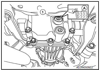
- Remove filler plug (1).
- Fill with new transfer oil to the specified level near the filler plug hole.
: front
Transfer oil grade and
viscosity
: Refer to MA-11, "Fluids and
Lubricants".
Transfer oil capacity : Refer to DLN-93, "General
Specifications".
- Set a new gasket onto filler plug, and install it in the transfer and tighten to specified torque. Refer to DLN- 89, "Exploded View".
CAUTION: Do not reuse gasket.
REAR PROPELLER SHAFT
REAR PROPELLER SHAFT : Inspection
APPEARANCE AND NOISE
- Check the propeller shaft tube surface for dents or cracks. If malfunction is detected, replace propeller shaft assembly.
- If center bearing is noisy or damaged, replace propeller shaft assembly.
VIBRATION
If vibration is present at high speed, adjust the propeller shaft phase first.
- Check the propeller shaft for bend and damage. If damaged, replace propeller shaft assembly.
- Perform a cruise test drive to check the propeller shaft for runout. If vibration occurs, separate propeller shaft at electric controlled coupling of final drive; then change the phase between electric controlled coupling stud bolt and propeller shaft by the one bolt hole at a time and install propeller shaft.
- If vibration is still detected, measure propeller shaft runout after removing it. Refer to DLN-101, "Inspection".
REAR DIFFERENTIAL GEAR OIL
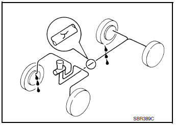
REAR DIFFERENTIAL GEAR OIL : Inspection
- Remove filler plug (1) and check oil level from filler plug mounting
hole as shown.
CAUTION: Do not start engine while checking oil level.
- Set a new gasket on filler plug and install it on final drive assembly.
Refer to DLN-124, "Exploded View".
CAUTION: Do not reuse gasket
REAR DIFFERENTIAL GEAR OIL : Draining
- Stop engine.
- Remove drain plug (1) and drain gear oil.
- Set a new gasket on drain plug and install it to final drive
assembly
and tighten to the specified torque. Refer to DLN-124,
"Exploded View".
CAUTION: Do not reuse gasket.
REAR DIFFERENTIAL GEAR OIL : Refilling
- Remove filler plug (1). Fill with new gear oil until oil level reaches the specified level near filler plug hole.
Oil grade and viscosity : Refer to MA-11, "Fluids
and Lubricants".
Oil capacity : Refer to DLN-141, "General
Specifications".
- After refilling oil, check oil level. Set a new gasket to filler plug, then install it to final drive assembly. Refer to DLN-124, "Exploded View".
CAUTION: Do not reuse gasket.
WHEELS
WHEELS : Inspection
WHEEL
- Check tires for wear and improper inflation.
- Check wheels for deformation, cracks and other damage. If deformed, remove wheel and check wheel runout.
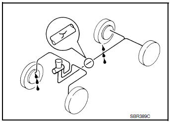
- Remove tire from wheel and mount wheel on a balancer machine.
- Set dial indicator as shown.
- Check runout, if runout value exceeds the limit, replace wheel.
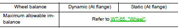
Limit
Axial Runout (A) Refer to WT-65, "Wheel".
Radial Runout (B) Refer to WT-65, "Wheel".
WHEELS : Adjustment
BALANCING WHEELS (ADHESIVE WEIGHT TYPE)
Preparation Before Adjustment
Remove inner and outer balance weights from the wheel. Using releasing agent, remove double-faced adhesive tape from the wheel and tire.
CAUTION:
- Be careful not to scratch the wheel and tire during removal.
- After removing double-faced adhesive tape, wipe clean all traces of releasing agent from the wheel and tire.
Wheel Balance Adjustment
CAUTION:
- DO NOT use center hole cone-type clamping machines to hold the wheel during tire removal/installation or balancing or damage to the wheel paint, cladding or chrome may result. Use only rim-type or universal lug-type clamping machines to hold the wheel during servicing.
- If a balancer machine has an adhesive weight mode setting, select the adhesive weight mode setting and skip Step 2 below. If a balancer machine only has the clip-on (rim flange) weight mode setting, follow Step 2 to calculate the correct size adhesive weight.
- Set wheel and tire on balancer machine using the center hole as a guide. Start the balancer machine.
- For balancer machines that only have a clip-on (rim flange) weight mode setting, follow this step to calculate the correct size adhesive weight to use. When inner and outer imbalance values are shown on the balancer machine indicator, multiply outer imbalance value by 5/3 (1.67) to determine balance weight that should be used. Select the outer balance weight with a value closest to the calculated value above and install in to the designated outer position of or at the designated angle in relation to the wheel and tire.
- Indicated imbalance value –ß 5/3 (1.67) = balance weight to be installed
Calculation example: 23 g (0.81 oz) –ß 5/3 (1.67) = 38.33 g (1.35 oz) ⇒ 40 g (1.41 oz) balance weight (closer to calculated balance weight value)
NOTE: Note that balance weight value must be closer to the calculated balance weight value.
Example:
37.4 ⇒ 35 g (1.23 oz)
37.5 ⇒ 40 g (1.41 oz)
- Install balance weight in the position shown.
CAUTION:
- Do not install the inner balance weight before installing the outer balance weight.
- Before installing the balance weight, be sure to clean the mating surface of the wheel and tire.
- When installing balance weight (1) to wheel and tire, set it into the grooved area (A) on the inner wall of the wheel and tire as shown so that the balance weight center (B) is aligned with the balancer machine indication position (angle) (C).
CAUTION:
- Always use Genuine NISSAN adhesive balance weights.
- Balance weights are non-reusable; always replace with new ones.
- Do not install more than three sheets of balance weights.
- If calculated balance weight value exceeds 50 g (1.76 oz), install
two balance weight sheets in line with each other as shown.
CAUTION: Do not install one balance weight sheet on top of another.
- Start balancer machine again.
- Install balance weight on inner side of wheel and tire in the
balancer
machine indication position (angle).
CAUTION: Do not install more than two balance weights.
- Start balancer machine. Make sure that inner and outer residual imbalance values are 5 g (0.17 oz) each or below.
- If either residual imbalance value exceeds 5 g (0.17 oz), repeat installation procedures.
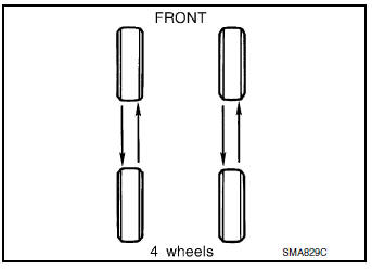
TIRE ROTATION
- Follow the maintenance schedule for tire rotation service
intervals.
Refer to MA-7, "Introduction of Periodic Maintenance".
- Rotate the wheels and tires front to back in the pattern as shown.
- When installing the wheel, tighten wheel nuts to the specified torque.MA-7, "Introduction of Periodic Maintenance"
WARNING:
- Do not include the spare tire (if equipped) when rotating tires.
- After rotating tires, check and adjust the tire pressure.
CAUTION:
- When installing wheel nuts, tighten them diagonally by dividing the work two to three times in order to prevent the wheels from developing any distortion.
- Be careful not to tighten the wheel nuts to a torque exceeding specification to prevent strain on the disc brake rotor.
- Use Genuine NISSAN wheel nuts.
Wheel nut tightening torque : WT-65, "Wheel"
- Perform the ID registration after tire rotation. Refer to WT-21, "Work Procedure".
BRAKE LINES AND CABLES
BRAKE LINES AND CABLES : Inspection
- Check brake fluid lines and parking brake cables for improper attachment, leaks, chafing, abrasions, deterioration, etc.
BRAKE FLUID
BRAKE FLUID : Inspection
BRAKE FLUID LEVEL
- Make sure that the brake fluid level in the reservoir tank is between the MAX and MIN lines.
- Visually check around the reservoir tank for brake fluid leakage.
- If the brake fluid level is excessively low, check the brake system for leakage.
- If brake warning lamp remains illuminated after parking brake pedal is released, check the brake system for brake fluid leakage.
BRAKE LINE
- Check brake line (tubes and hoses) for cracks, deterioration or other damage. Replace any damaged parts.
- Check for brake fluid leakage by fully depressing brake pedal while engine is running.
CAUTION: If brake fluid leakage occurs around joints, retighten or replace damaged parts as necessary.
BRAKE FLUID : Drain and Refill
CAUTION:
- Do not spill or splash brake fluid on painted surfaces. Brake fluid may damage paint. If brake fluid is splashed on painted areas, wash it away with water immediately.
- Prior to repair, turn the ignition switch OFF, disconnect the ABS actuator and electric unit (control unit) connector or negative battery terminal. Refer to PG-75, "Removal and Installation (Battery)".
- Refill brake system with new brake fluid. Refer to MA-11, "Fluids and Lubricants".
- Do not reuse drained brake fluid.
DRAINING
- Turn ignition switch OFF and disconnect ABS actuator and electric unit (control unit) connector or negative battery terminal. Refer to PG-75, "Removal and Installation (Battery)".
- Connect a vinyl tube to bleeder valve.
- Depress brake pedal, loosen bleeder valve, and gradually remove brake fluid.
CAUTION: Do not allow master cylinder reservoir tank to empty as this may cause damage to master cylinder internal components.
REFILLING
- Make sure no foreign material is in the reservoir tank, and refill
with new brake fluid.
CAUTION: Do not reuse drained brake fluid.
- Refill the brake system as follows:
- Depress the brake pedal.
- Loosen bleeder valve.
- Slowly depress brake pedal to 2/3 of the brake pedal full stroke.
- Tighten bleeder valve.
- Release brake pedal.
Repeat this operation at intervals of two or three seconds until all old brake fluid is discharged. Add new brake fluid frequently.
CAUTION: Do not allow master cylinder reservoir tank to empty as this may cause damage to master cylinder internal components.
- Bleed the air out of the brake hydraulic system. Refer to BR-16, "Bleeding Brake System".
FRONT BRAKE
FRONT BRAKE : Inspection
Check brake pad wear thickness from an inspection hole (A) on cylinder body. Check using a scale if necessary.
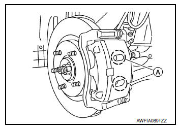
Wear thickness : Refer to BR-55, "Front Disc Brake".
FRONT BRAKE : Inspection
APPEARANCE
Check surface of disc brake rotor for uneven wear, cracks or damage. Replace if any abnormal conditions exist.
RUNOUT
- Check the wheel bearing axial end play before the inspection. Refer to FAX-7, "Inspection"(FWD) or FAX- 38, "Inspection"(AWD).
- Secure the disc brake rotor to the wheel hub and bearing with wheel nuts at two wheel nut locations.
- Inspect the runout with a dial gauge, measured at 10 mm (0.39 in) inside the disc brake rotor edge.
Runout : Refer to BR-55, "Front Disc Brake".
- Find the installation position with a minimum runout by shifting the disc brake rotor-to-wheel hub and bearing installation position by one hole at a time if the runout exceeds the limit value.
- Refinish the disc brake rotor if the runout is outside the limit even after performing the above operation. When refinishing, use Tool.
Tool number : 38-PFM92
CAUTION:
- Check in advance that the thickness of the disc brake rotor is wear thickness + 0.3 mm (0.012 in) or more.
- If the thickness is less than wear thickness + 0.3 mm (0.012 in), replace the disc brake rotor.
Wear thickness : Refer to BR-55, "Front Disc Brake".
THICKNESS
Check the thickness of the disc brake rotor using a micrometer.
Replace the disc brake rotor if the thickness is below the wear limit.
Wear thickness : Refer to BR-55, "Front Disc
Brake".
Thickness variation : Refer to BR-55, "Front Disc
Brake".
REAR BRAKE
REAR BRAKE : Inspection
INSPECTION
Check brake pad wear thickness from an inspection hole (A) on cylinder body. Check using a scale if necessary.
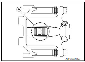
Wear thickness : Refer to BR-55, "Rear Disc Brake".
REAR BRAKE : Inspection
Appearance
Check surface of disc brake rotor for uneven wear, cracks or damage. Replace if any abnormal conditions exist.
Runout
- Check the wheel bearing axial end play before the inspection. Refer to RAX-6, "Inspection"(FWD) or RAX- 14, "Inspection"(AWD)
- Secure the disc brake rotor to the wheel hub and bearing with wheel nuts at two wheel nut locations.
- Measure the runout with a dial gauge 10 mm (0.39 in) from the disc brake rotor edge.
Runout : Refer to BR-55, "Rear Disc Brake".
- Find the installation position with a minimum runout by shifting the disc brake rotor-to-wheel hub and bearing installation position by one hole at a time if the runout exceeds the limit value.
- Refinish the disc brake rotor if the runout is outside the limit even after performing the above operation. When refinishing, use Tool.
Tool number : 38-PFM92
CAUTION:
- Check in advance that the thickness of the disc brake rotor is wear thickness + 0.3 mm (0.012 in) or more.
- If the thickness is less than wear thickness + 0.3 mm (0.012 in), replace the disc brake rotor.
Wear thickness : Refer to BR-55, "Rear Disc Brake".
Thickness
Check the thickness of the disc brake rotor using a micrometer.
Replace the disc brake rotor if the thickness is below the minimum thickness.
Minimum thickness : Refer to BR-55, "Rear Disc
Brake".
Thickness variation : Refer to BR-55, "Rear Disc
Brake".
STEERING GEAR AND LINKAGE
STEERING GEAR AND LINKAGE : Inspection
STEERING GEAR
- Check gear housing and boots for looseness, damage and grease leakage.
- Check connection with steering column for looseness.
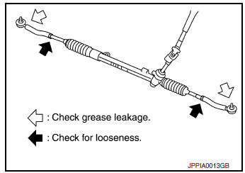
STEERING LINKAGE
Check ball joint, dust cover and other component parts for looseness, wear, damage and grease leakage.
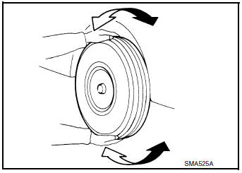
AXLE AND SUSPENSION PARTS
AXLE AND SUSPENSION PARTS : Inspection
Check front and rear axle and suspension parts for excessive play, cracks, wear or other damage.
- Shake each wheel to check for excessive play.
- Check wheel bearings for smooth operation.
- Check axle and suspension nuts and bolts for looseness.
- Check strut (shock absorber) for oil leakage or other damage.
- Check suspension ball joint for grease leakage and ball joint dust cover for cracks or other damage.
DRIVE SHAFT
DRIVE SHAFT : Inspection
- Check boot and drive shaft for cracks, wear, damage and grease leakage.
LOCKS, HINGES AND HOOD LATCH
LOCKS, HINGES AND HOOD LATCH : Lubricating
WITH INTELLIGENT KEY SYSTEM
For hood and hood lock illustration.
- Hood: Refer to DLK-233, "Exploded View".
- Hood lock control: Refer to DLK-233, "Exploded View".
For front door and front door lock illustration.
- Front door: Refer to DLK-240, "Exploded View".
- Front door lock: Refer to DLK-256, "Exploded View".
- Rear door: Refer to DLK-244, "Exploded View".
- Rear door lock: Refer to DLK-260, "Exploded View".
For back door and back door lock illustration.
- Back door: Refer to DLK-248, "Exploded View".
- Back door lock: Refer to DLK-263, "Exploded View".
WITHOUT INTELLIGENT KEY SYSTEM
For hood and hood lock illustration.
- Hood: Refer to DLK-350, "Exploded View".
- Hood lock control: Refer to DLK-370, "Exploded View".
For front door and front door lock illustration.
- Front door: Refer to DLK-357, "Exploded View".
- Front door lock: Refer to DLK-377, "Exploded View".
- Rear door: Refer to DLK-361, "Exploded View".
- Rear door lock: Refer to DLK-377, "Exploded View".
For back door and back door lock illustration.
- Back door: Refer to DLK-365, "Exploded View".
- Back door lock: Refer to DLK-380, "Exploded View".
SEAT BELT, BUCKLES, RETRACTORS, ANCHORS AND ADJUSTERS
SEAT BELT, BUCKLES, RETRACTORS, ANCHORS AND ADJUSTERS : Inspection
For front seat belt illustration. Refer to SB-8, "Exploded View".
For rear seat belt illustration. Refer to SB-12, "Exploded View".
CAUTION:
- After any collision, inspect all seat belt assemblies,
including retractors and other attached hardwares
(I.e. anchor bolt, guide rail set). Nissan recommends to replace all seat
belt assemblies in use
during a collision, unless not damaged and properly operating after minor
collision.
Also inspect seat belt assemblies not in use during a collision, and replace if damaged or improperly operating.
Seat belt pre-tensioner should be replaced even if the seat belts are not in use during a frontal collision where the driver and passenger air bags are deployed.
- If any component of seat belt assembly is questionable, do not
repair.
Replace as seat belt assembly.
- If webbing is cut, frayed, or damaged, replace belt assembly.
- Never oil tongue and buckle.
- Use a genuine NISSAN seat belt assembly.
For details, refer to SB-5, "Inspection" in SB section.
- Check anchors for loose mounting
- Check belts for damage
- Check retractor for smooth operation
- Check function of buckles and tongues when buckled and released
 Engine maintenance
DRIVE BELTS
DRIVE BELTS : Exploded View
Generator pulley
Water pump pulley
Drive belt auto-tensioner
Crankshaft pulley
A/C compressor pulley
Drive belt retainer boss
&nb ...
Other materials:
Door mirror
Exploded View
Door mirror
Door mirror corner finisher
Door mirror rear finisher
Side turn signal lamp
Side camera (if equipped)
Door mirror glass
Pawl
Removal and Installation
REMOVAL
Remove front door finisher. Refer to INT-15, "Removal and
...
Unit disassembly and assembly
FRONT DRIVE SHAFT
Exploded View (LH)
Shaft
Circular clip
Dust shield
Housing
Snap ring
Spider assembly
Stopper ring
Boot
Boot band
Joint sub-assembly
Wheel side
Disassembly and Assembly (LH)
DISASSEMBLY
Transaxle Assembly Side
Fix shaft ...
Removal and installation
BCM (BODY CONTROL MODULE)
Removal and Installation
For removal and installation of the BCM (Body Control Module), refer to
BCS-75, "Removal and Installation".
PUSH-BUTTON IGNITION SWITCH
Removal and Installation
REMOVAL
Remove NATS antenna amp. Refer to SEC-110, "Remo ...
