Nissan Rogue (T33) 2021-Present Service Manual: Component Parts
Adas Control Unit
Without Propilot Assist 2.1
Component Parts Location
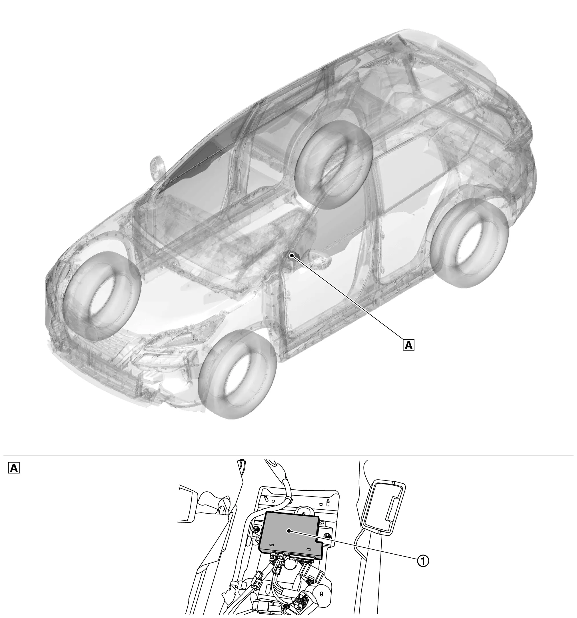
| A. | View with center console assembly removed |
| No. | Component | Function |
|---|---|---|
| 1. | ADAS (Advanced Driver Assistant System) control unit 2 | Refer to ADAS Control Unit 2. |
With Propilot Assist 2.1
Component Parts Location
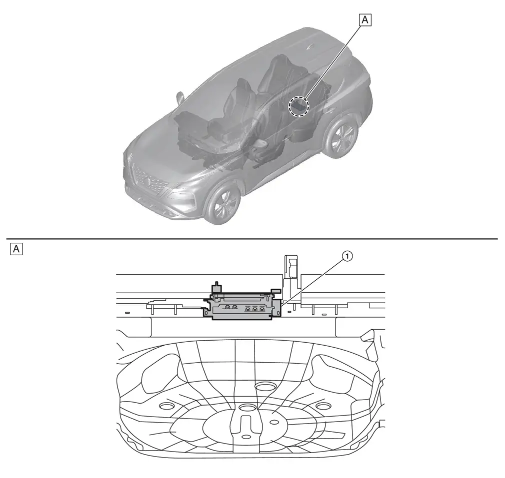
| A. | View with luggage floor board removed |
| No. | Component | Function |
|---|---|---|
| 1. | ADAS (Advanced Driver Assistant System) control unit 2 | Refer to ADAS Control Unit 2. |
ADAS Control Unit
Without ProPILOT Assist 2.1
FUNCTIONS WITHIN THE SYSTEM
-
ADAS control unit 2 controls the following systems, based on CAN communication signal from each control unit.
-
AEB
-
RAB
-
ProPILOT Assist 1.1
-
I-FCW
-
LDW
-
I-LI
-
I-BSI
-
I-DA
-
INDIVIDUAL FUNCTIONS WITHIN THE SYSTEM
-
Transmits the signals to each control unit via CAN communication.
-
Receives the signals from each control unit via CAN communication
INDIVIDUAL OPERATION
-
AEB: Refer to System Description.
-
RAB: Refer to System Description.
-
ProPILOT Assist 1.1: Refer to System Description.
-
I-FCW: Refer to System Description.
-
LDW: Refer to System Description.
-
I-LI: Refer to System Description.
-
I-BSI: Refer to System Description.
-
I-DA: Refer to System Description.
PARTS LOCATION
Refer to Component Parts Location.
With ProPILOT Assist 2.1
FUNCTIONS WITHIN THE SYSTEM
-
ADAS control unit 2 controls the following systems, based on CAN communication signal from each control unit.
-
AEB
-
RAB
-
ProPILOT Assist 2.1
-
I-FCW
-
I-LI
-
I-BSI
-
I-DA
-
LDW
-
TSR
-
INDIVIDUAL FUNCTIONS WITHIN THE SYSTEM
-
Transmits the signals to each control unit via CAN communication.
-
Receives the signals from each control unit via CAN communication
INDIVIDUAL OPERATION
-
AEB: Refer to System Description.
-
RAB: Refer to System Description.
-
ProPILOT Assist 2.1: Refer to System Description.
-
I-FCW: Refer to System Description.
-
I-LI: Refer to System Description.
-
I-BSI: Refer to System Description.
-
I-DA: Refer to System Description.
-
LDW: Refer to System Description.
-
TSR: Refer to System Description.
PARTS LOCATION
Refer to Component Parts Location.
Other materials:
Modes de fonctionnement des essuie-glaces
Type A (selon Ă©quipement)
Type B (selon Ă©quipement)
Les commandes de visibilité de votre Nissan Rogue s'activent lorsque le contact est sur "ON" :
Mode AUTO / Intermittent :
- Type A (Automatique) : Le Nissan Rogue ajuste seul la vitesse selon l'intensité de la pluie ...
If your vehicle overheats
WARNING
Never continue driving if your vehicle overheats — this can lead to engine failure or even a vehicle fire.
Never open the hood if steam is coming out.
Never remove the radiator or coolant reservoir cap when the engine is hot. Pressurized coolant can spray out and cause serious ...
Dtc/circuit Diagnosis. B2906-11 Recliner Sensor
DTC Description
DTC DETECTION LOGIC DTC No.
CONSULT screen items
(Trouble diagnosis content) DTC detection condition
B2906-11
Recliner Sensor
Diagnosis condition
The Recliner Sensor signal is shorted to ground
Signal (terminal)
Reclining Motor (terminal #5)
Threshold
...