Nissan Rogue (T33) 2021-Present Service Manual: Chassis Control :: Ecu Diagnosis Information. Chassis Control Module
Chassis Control Module
Without Telematics System
Reference Value
 NOTE:
NOTE:
The following table includes information (items) inapplicable to this Nissan Ariya vehicle. For information (items) applicable to this vehicle, refer to CONSULT display items.
| Monitor item | Condition | Reference values in normal operation |
|---|---|---|
| Battery voltage | Always | 6 - 16 V |
| ACC voltage | When ignition switch ACC | 6 - 16 V |
| Control module malfunction status | When chassis control module is normal | Off |
| When chassis control module is malfunction | On | |
| Diagnosis permission condition | When not communication | Not permission |
| When communication | Permission | |
| When communication is malfunction*1 | Abnormal | |
| Chassis control malfunction display | When chassis control warning is dysplayed | On |
| When chassis control warning is not displayed | Off | |
| Nissan Ariya VehicleSpeed1 | When vehicle stopped | 0 km/h |
| When Nissan Ariya vehicle driving*2 | Almost same reading as speedometer (Within ┬▒10%) | |
| Nissan Ariya Vehicle speed | When vehicle stopped | 0 km/h |
| When Nissan Ariya vehicle driving*2 | Almost same reading as speedometer (Within ┬▒10%) | |
| Front right wheel speed | When Nissan Ariya vehicle stopped | 0 rpm |
| When vehicle driving*2 | Increases according to Nissan Ariya vehicle speed | |
| Front left wheel speed | When Nissan Ariya vehicle stopped | 0 rpm |
| When Nissan Ariya vehicle driving*2 | Increases according to vehicle speed | |
| Rear right wheel speed | When Nissan Ariya vehicle stopped | 0 rpm |
| When Nissan Ariya vehicle driving*2 | Increases according to vehicle speed | |
| Rear left wheel speed | When Nissan Ariya vehicle stopped | 0 rpm |
| When Nissan Ariya vehicle driving*2 | Increases according to vehicle speed | |
| Steering angle sensor | When Nissan Ariya vehicle driving straight | 0┬▒2.5 deg |
| When steering wheel is steered to RH by 90┬░ | Approx. ŌłÆ90 deg | |
| When steering wheel is steered to LH by 90┬░ | Approx. +90 deg | |
| Decel G sensor | Nissan Ariya Vehicle stopped | Approx. 0 G |
| When during acceleration | Positive value | |
| When during deceleration | Negative value | |
| Decel G | Nissan Ariya Vehicle stopped | Approx. 0 G |
| When during acceleration | Positive value | |
| When during deceleration | Negative value | |
| Side G sensor | Nissan Ariya Vehicle stopped | Approx. 0 G |
| When right turn | Negative value | |
| When left turn | Positive value | |
| Yaw rate sensor | Nissan Ariya Vehicle stopped | Approx. 0 deg/s |
| When right turn | Negative value | |
| When left turn | Positive value | |
| Accelerator pedal position | When accelerator pedal is released | 0% |
| When accelerator pedal is depressed | 0 ŌłÆ 100% | |
| Pressure sensor | When brake pedal is not depressed | Approx. 0 bar |
| When brake pedal is depressed | 0 ŌłÆ 255 bar | |
| Throttle control | When electric throttle control actuator is normal | Normal |
| When the engine torque command cannot be executed correctly | Abnormal 1 | |
| When the engine torque command cannot be executed (transient state) | Abnormal 2 | |
| When the engine torque command cannot be executed | Abnormal 3 | |
| Shift position | When ignition switch ON | Indicates selected electric shift selector position |
| Shift position(R) | When electric shift selector position is other R | Not R |
| When electric shift selector position is R | R | |
| When electric shift selector is malfunction | Abnormal | |
| Stop lamp switch | When brake pedal is not depressed | Brake pedal not operation |
| When brake pedal is depressed | Brake pedal operation 1 | |
| When brake pedal being depressed is confirmed | Brake pedal operation 2 | |
| When stop lamp switch is malfunction*1 | Abnormal | |
| ABS | When ABS function is inactive | Inactive |
| When ABS function is active | Active | |
| ABS malfunction | When ABS function is malfunction | On |
| When ABS function is not malfunction | Off | |
| EBD | When EBD function is inactive | Inactive |
| When EBD function is active | Active | |
| TCS | When TCS function is malfunction | Inactive |
| When TCS function is normal | Active | |
| TCS malfunction | When TCS function is malfunction | On |
| When TCS function is not malfunction | Off | |
| VDC | When VDC function is inactive | Inactive |
| When VDC function is active | Active | |
| VDC malfunction | When VDC function is malfunction | On |
| When VDC function is not malfunction | Off | |
| VDC OFF switch | When VDC OFF function is ON | On |
| When VDC OFF function is OFF | Off | |
| Intelligent cruise control brake active status | When intelligent cruise control function (braking) is permitted | Permit |
| When intelligent cruise control function (braking) is not permitted | Not permission | |
| When intelligent cruise control function (braking) is malfunction*1 | Abnormal | |
| Yaw rate (ADAS) | ŌĆö | Displays but not used |
| ProPILOT park | ŌĆö | Displays but not used |
| Brake torque request | When braking is controlled by active ride control | Depends on the command value |
| When braking is not controlled by active ride control | 0 Nm | |
| Parking brake operation status | When electric parking brake system is release | Release |
| When electric parking brake system is apply | Apply | |
| When electric parking brake function is malfunction*1 | Abnormal | |
| Stop hold (VDC) | When stop hold status is release | Release |
| When stop hold status is active | Apply | |
| When stop hold status is impossible | Impossible | |
| Front right wheel speed pulse (stop hold) | When Nissan Ariya vehicle stopped | 0 |
| When vehicle driving*2 | Increases according to Nissan Ariya vehicle speed | |
| Front left wheel speed pulse (stop hold) | When Nissan Ariya vehicle stopped | 0 |
| When vehicle driving*2 | Increases according to Nissan Ariya vehicle speed | |
| Rear right wheel speed pulse (stop hold) | When Nissan Ariya vehicle stopped | 0 |
| When vehicle driving*2 | Increases according to Nissan Ariya vehicle speed | |
| Rear left wheel speed pulse (stop hold) | When Nissan Ariya vehicle stopped | 0 |
| When vehicle driving*2 | Increases according to Nissan Ariya vehicle speed | |
| Command brake torque (Cruise control system) | ŌĆö | Displays but not used |
| Command brake torque (HPCM) | ŌĆö | Displays but not used |
| Command brake torque value (ADAS) 1 | When no brake torque command from ADAS control unit 2 | 0 Nm |
| When brake torque command from ADAS control unit 2 | Change according to brake command from ADAS control unit 2 | |
| Command brake torque value (ADAS) 2 | ŌĆö | Displays but not used |
| Regenerative brake request (HPCM) | ŌĆö | Displays but not used |
| Driver brake torque request | ŌĆö | Displays but not used |
| Cruise Control / Speed Limiter active status 1 | ŌĆö | Displays but not used |
| Yaw control status | ŌĆö | Displays but not used |
| Control status (VDC) 1 | ŌĆö | Displays but not used |
| Control status (VDC) 2 | When VDC function activation is impossible | Impossible |
| When VDC function activation is possible | Possible | |
| Maintenance mode status | ŌĆö | Displays but not used |
| Regenerative brake status (VDC) | ŌĆö | Displays but not used |
| Engine control status 1 | ŌĆö | Displays but not used |
| Engine control status 2 | ŌĆö | Displays but not used |
| Cruise Control / Speed Limiter active status 2 | ŌĆö | Displays but not used |
| Brake active request (ADAS) 1 | ŌĆö | Displays but not used |
| Brake active request (ADAS) 2 | When not requested by ADAS control unit 2 | Inactive |
| When requested (electric parking brake system) by ADAS control unit 2 | Request 1 | |
| When requested (other than electric parking brake system) by ADAS control unit 2 | Request 2 | |
| Brake active request (ADAS) 3 | ŌĆö | Displays but not used |
| Rear wheel steering status 1 | ŌĆö | Displays but not used |
| Rear wheel steering status 2 | ŌĆö | Displays but not used |
| Intelligent trace control/Active trace control status 2 | When intelligent trace control function is normal | Normal |
| When intelligent trace control function is malfunction | Malfunction | |
| Intelligent trace control/Active trace control status 3 | When intelligent trace control function is normal | Normal |
| When intelligent trace control function is malfunction | Malfunction | |
| Intelligent trace control/Active trace control status 4 | When intelligent trace control function is normal | Normal |
| When intelligent trace control function is malfunction | Malfunction | |
| Intelligent trace control/Active trace control status 5 | When intelligent trace control function is normal | Normal |
| When intelligent trace control function is malfunction | Malfunction | |
| Intelligent trace control/Active trace control status (engine control) 1 | ŌĆö | Displays but not used |
| Intelligent trace control/Active trace control status (engine control) 2 | ŌĆö | Displays but not used |
| Intelligent trace control/Active trace control status (brake control) 1 | ŌĆö | Displays but not used |
| Intelligent trace control/Active trace control status (brake control) 2 | ŌĆö | Displays but not used |
| Intelligent engine brake/Active engine brake status 1 | ŌĆö | Displays but not used |
| Intelligent engine brake/Active engine brake status 2 | ŌĆö | Displays but not used |
| Intelligent ride control/Active ride control status 1 | When active ride control function is normal | Normal |
| When active ride control function is malfunction | Malfunction | |
| Intelligent ride control/Active ride control status 2 | When active ride control function is normal | Normal |
| When active ride control function is malfunction | Malfunction | |
| Chassis control (ADAS) 1 | When normal (judgment by ADAS control unit 2) | Normal |
| When malfunction (judgment by ADAS control unit 2) | Malfunction | |
| Chassis control (ADAS) 2 | ŌĆö | Displays but not used |
| Intelligent ride control/Active ride control status 3 | When active ride control function is normal | Normal |
| When active ride control function is malfunction | Malfunction | |
| Intelligent ride control/Active ride control status 4 | When active ride control function is normal | Normal |
| When active ride control function is malfunction | Malfunction | |
| Intelligent cruise control status | When intelligent cruise control function is OFF | Off |
| When intelligent cruise control function is operation | Operation | |
| When intelligent cruise control function is stop | Stop | |
| When intelligent cruise control function is wait | Wait | |
| When intelligent cruise control function is suspended | Suspend | |
| When intelligent cruise control function is brake mode | Brake mode | |
| When intelligent cruise control function is regulation | Regulation | |
| When intelligent cruise control function is driver override | Driver override | |
| When intelligent cruise control function is malfunction | Malfunction | |
| When intelligent cruise control function is abnormal | Abnormal | |
| Automatic brake hold warning display request | When automatic brake hold warning is not displayed | No request |
| When automatic brake hold warning is displayed | Request | |
| Automatic brake hold select status | When automatic brake hold function is OFF mode | OFF mode |
| When automatic brake hold function is auto mode | AUTO mode | |
| Automatic brake hold status 1 | When automatic brake hold function is inactive | Inactive |
| When automatic brake hold function is active | Active | |
| Automatic brake hold status 2 | When automatic brake hold function is inactive | Inactive |
| When automatic brake hold function is active | Active | |
| Electric parking brake active request (automatic brake hold) | When electric parking brake system is inactive by chassis control module | No request |
| When electric parking brake system is active by chassis control module | Request | |
| Automatic brake hold stop hold request status 2 | When stop hold of automatic brake hold function is not requested | Not used |
| When stop hold of automatic brake hold function is requested | Request | |
| Automatic brake hold status 3 | When automatic brake hold function is inactive | No request |
| When automatic brake hold function is active | Request | |
| ProPILOT stop hold status | When automatic brake hold function by ProPILOT is inactive (current) | Inactive |
| When automatic brake hold function by ProPILOT is active (current) | Active | |
| Electric parking brake active request (ProPILOT) | When active of electric parking brake function is not requested by ADAS control unit 2 | No request |
| When active of electric parking brake function is not requested by ADAS control unit 2 | Request | |
| Automatic brake hold active request (ProPILOT) | When active of automatic brake hold function is not requested by ADAS control unit 2 | No request |
| When active of automatic brake hold function is requested by ADAS control unit 2 | Request | |
| Automatic brake hold switch 2 | When automatic brake hold switch is not push | No push |
| When automatic brake hold switch is pushing | Push | |
| Automatic brake hold switch indicator 3 | When automatic brake hold switch indicator is turn ON | On |
| When automatic brake hold switch indicator is turn OFF | Off | |
| Drive mode selector status | Always | (Mode 0 - 30) |
| User | ŌĆö | Displays but not used |
| Drive Mode Selector (rotary) | Always (AWD models) | (Mode 0 - 255) |
| Engine/Transmission setting | ŌĆö | Displays but not used |
| Steering setting | ŌĆö | Displays but not used |
| 4WD setting | ŌĆö | Displays but not used |
| Intelligent trace control/Active trace control status | ŌĆö | Displays but not used |
| Intelligent cruise control setting | ŌĆö | Displays but not used |
| Intelligent Key link status | ŌĆö | Displays but not used |
| Log-in permission status | ŌĆö | Displays but not used |
| Drive mode selector (UP) | When not operated | Not operation |
| When operated (up) | Operation | |
| Drive mode selector (DOWN) | When not operated | Not operation |
| When operated (down) | Operation |
*1: It may be displayed when initializing communication.
*2: Check tire pressure under normal conditions.
TERMINAL LAYOUT
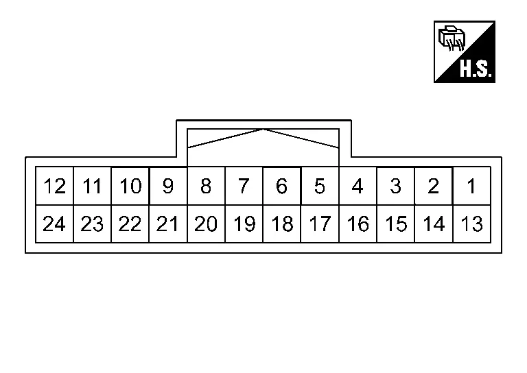
PHYSICAL VALUES
|
Terminal No. (Wire color) | Description | Condition | Value | |||
|---|---|---|---|---|---|---|
| + | ŌłÆ | Signal name | Input/Output | |||
|
3 (LA/GR) |
Ground | CAN-H | ŌĆö | ŌĆö | ŌĆö | ŌĆö |
|
4 (LA/R) |
CAN-L | ŌĆö | ŌĆö | ŌĆö | ŌĆö | |
|
5 (LA/G) |
Accessory power supply | Input | Ignition switch ON | 6 - 16 V | ||
|
7 (LA/V) |
CAN-L | ŌĆö | ŌĆö | ŌĆö | ŌĆö | |
|
8 (GR) |
CAN-H | ŌĆö | ŌĆö | ŌĆö | ŌĆö | |
|
9 (GR) |
CAN-H | ŌĆö | ŌĆö | ŌĆö | ŌĆö | |
|
13 (LA/Y) |
Battery power supply | ŌĆö | Always | 6 - 16 V | ||
|
15 (B) |
Ground | ŌĆö | Ignition switch ON | ŌĆö | Approx. 0 V | |
|
16 (LA/G) |
CAN-L | ŌĆö | ŌĆö | ŌĆö | ŌĆö | |
|
17 (LA/GR) |
CAN-H | ŌĆö | ŌĆö | ŌĆö | ŌĆö | |
|
19 (LA/GR) |
CAN-H | ŌĆö | ŌĆö | ŌĆö | ŌĆö | |
|
20 (G) |
CAN-L | ŌĆö | ŌĆö | ŌĆö | ŌĆö | |
|
21 (V) |
CAN-L | ŌĆö | ŌĆö | ŌĆö | ŌĆö | |
|
22 (LA/Y) |
Automatic brake hold switch indicator | Output | Ignition switch ON | Automatic brake hold function ON | Approx. 4 V | |
| Automatic brake hold function OFF | Approx. 12 V | |||||
|
24 (LA/SB) |
Automatic brake hold switch | Input | Ignition switch ON | Automatic brake hold switch is pushing | Approx. 0 V | |
Fail-safe
Refer to Fail-safe.
DTC Inspection Priority Chart
When multiple DTCs are displayed simultaneously, check them one by one according to the following priority list.
| Priority | Detected item (DTC) |
|---|---|
| 1 |
|
| 2 |
|
| 3 |
|
| 4 |
|
| 5 |
|
| 6 |
|
DTC Index
| DTC | Display item | Warning message | Refer to |
|---|---|---|---|
| C1B80-54 | Calibration not completed | ON | DTC Description |
| C1B81-55 | Configuration not completed | ON | DTC Description |
| C1B8F-82 | IPDM E/R communication | ON | DTC Description |
| C1B92-82 | Brake control system | ON | DTC Description |
| C1B93-82 | Engine/HEV system | ON | DTC Description |
| C1B94-82 | TM system | ON | DTC Description |
| C1B96-82 | ADAS SYSTEM | - | DTC Description |
| C1B97-82 | BCM | ON | DTC Description |
| C1BB4-44 | Control module | ON | DTC Description |
| C1BB4-45 | Control module | ON* | DTC Description |
| C1BB4-46 | Control module | ON | DTC Description |
| C1BB4-49 | Control module | ON* | DTC Description |
| U0076-00 | Control module communication Bus D Off | - | DTC Description |
| U007A-00 | Control module communication Bus H Off | - | DTC Description |
| U1327-52 | MAC key update | - | DTC Description |
| U1327-54 | MAC key update | - | DTC Description |
| U2118-87 | CAN communication error (Intelligent Key unit) | OFF | DTC Description |
| U2140-57 | CAN communication error (ECM) | - | DTC Description |
| U2140-83 | CAN communication error (ECM) | ON | DTC Description |
| U2140-87 | CAN communication error (ECM) | ON | DTC Description |
| U214F-57 | CAN communication error (BCM) | - | DTC Description |
| U214F-83 | CAN communication error (BCM) | ON | DTC Description |
| U214F-87 | CAN communication error (BCM) | ON* | DTC Description |
| U2152-57 | CAN communication error (ADAS control unit) | - | DTC Description |
| U2152-83 | CAN communication error (ADAS control unit) | - | DTC Description |
| U2152-87 | CAN communication error (ADAS control unit) | - | DTC Description |
| U2154-87 | CAN communication error (AV control unit) | - | DTC Description |
| U215B-83 | CAN communication error (IPDM E/R) | ON | DTC Description |
| U215B-87 | CAN communication error (IPDM E/R) | ON | DTC Description |
| U2165-57 | CAN communication error (sonar control unit) | - | DTC Description |
| U2248-83 | CAN communication error [ABS actuator and electric unit (control unit)] | ON | DTC Description |
| U2248-87 | CAN communication error [ABS actuator and electric unit (control unit)] | ON | DTC Description |
| U2448-87 | CAN communication error [ABS actuator and electric unit (control unit)] | ON | DTC Description |
| U2541-83 | CAN communication error (TCM) | ON | DTC Description |
| U2541-87 | CAN communication error (TCM) | ON | DTC Description |
| U2A03-88 | Communication Bus Off CH-FD | - | DTC Description |
| U2A0B-88 | Communication Bus Off CH2-CAN | - | DTC Description |
| U2A0E-88 | Communication Bus Off CH2-FD | - | DTC Description |
*: Chassis control warning in information display turns ON/OFF according to a condition when DTC is detected.
With Telematics System
Reference Value
NOTE:
The following table includes information (items) inapplicable to this Nissan Ariya vehicle. For information (items) applicable to this vehicle, refer to CONSULT display items.
| Monitor item | Condition | Reference values in normal operation | |
|---|---|---|---|
| Battery voltage | Always | 6 - 16 V | |
| ACC voltage | When ignition switch ACC | 6 - 16 V | |
| Control module malfunction status | When chassis control module is malfunction | ŌĆö | |
| Diagnosis permission condition | When not communication | Not permission | |
| When communication | Permission | ||
| When communication is malfunction*1 | Abnormal | ||
| Chassis control malfunction display | When chassis control warning is not displayed | Off | |
| When chassis control warning is displayed | On | ||
| Nissan Ariya VehicleSpeed1 | When vehicle stopped | 0 km/h | |
| When Nissan Ariya vehicle driving*2 | Increases according to vehicle speed | ||
| Nissan Ariya Vehicle speed | When vehicle stopped | 0 km/h | |
| When Nissan Ariya vehicle driving*2 | Increases according to vehicle speed | ||
| Front right wheel speed | When Nissan Ariya vehicle stopped | 0 km/h | |
| When vehicle driving*2 | Increases according to Nissan Ariya vehicle speed | ||
| Front left wheel speed | When vehicle stopped | 0 km/h | |
| When Nissan Ariya vehicle driving*2 | Increases according to vehicle speed | ||
| Rear right wheel speed | When Nissan Ariya vehicle stopped | 0 km/h | |
| When vehicle driving*2 | Increases according to Nissan Ariya vehicle speed | ||
| Rear left wheel speed | When vehicle stopped | 0 km/h | |
| When Nissan Ariya vehicle driving*2 | Increases according to vehicle speed | ||
| Steering angle sensor | When Nissan Ariya vehicle driving straight | 0┬▒2.5┬░ | |
| When steering wheel is steered to LH by 90┬░ | Approx. +90┬░ | ||
| When steering wheel is steered to RH by 90┬░ | Approx. -90┬░ | ||
| Yaw rate sensor | When Nissan Ariya vehicle stopped | Approx. 0 deg/s | |
| When left turn | Positive value | ||
| When right turn | Negative value | ||
| Accelerator pedal position | When accelerator pedal is released | 0% | |
| When accelerator pedal is depressed | 0 - 100% | ||
| Pressure sensor | When brake pedal is not depressed | Approx. 0 bar | |
| When brake pedal is depressed | 0 - 255 bar | ||
| Throttle control | ŌĆö | Displays but not used. | |
| Shift position | When ignition switch ON | Indicates selected electric shift selector position | |
| Shift position (R) | When electric shift selector position is other R | Not R | |
| When electric shift selector position is R | R | ||
| When electric shift selector is malfunction | Abnormal | ||
| Stop lamp switch | When brake pedal is not depressed | Brake pedal not operation | |
| When brake pedal is depressed | Brake pedal operation 1 | ||
| When brake pedal being depressed is confirmed | Brake pedal operation 2 | ||
| When stop lamp switch is malfunction*1 | Abnormal | ||
| Brake pedal operation status | When brake pedal is not depressed | Not depressed | |
| When brake pedal is depressed | Depressed slightly | ||
| When stop lamp switch is malfunction | Abnormal | ||
| ABS | When ABS function is inactive | Inactive | |
| When ABS function is active | Active | ||
| ABS malfunction | When ABS function is normal | Off | |
| When ABS function is malfunction | On | ||
| EBD | When EBD function is inactive | Inactive | |
| When EBD function is active | Active | ||
| TCS | When TCS function is inactive | Inactive | |
| When TCS function is active | Active | ||
| TCS malfunction | When TCS function is normal | Off | |
| When TCS function is malfunction | On | ||
| VDC | When VDC function is inactive | Inactive | |
| When VDC function is active | Active | ||
| VDC malfunction | When VDC function is normal | Off | |
| When VDC function is malfunction | On | ||
| VDC OFF switch | When VDC OFF switch is OFF | Off | |
| When VDC OFF switch is ON | On | ||
| Firmware Over-The-Air status | While waiting to receive the update data | Waiting | |
| While receiving the update data | Receiving | ||
| While copying the update data | Copying | ||
| While checking the Nissan Ariya vehicle status | Checking the vehicle status | ||
| While preparing to write the update data | Preparing to start | ||
| While switching to write work | Switching | ||
| While chassis control module is reboot | Rebooting | ||
| While checking the write data version | Checking the version | ||
| While writing | Configuration is running | ||
| Completed chassis control module startup | Startup complete | ||
| While detecting to the write error | Error1 | ||
| Canceling write | Canceling | ||
| While updating to the write error | Error2 | ||
| During rollback to the write data | During rollback | ||
| Completed rollback to the write data | Rollback complete | ||
| Internal area 1 program updates counter | Always | Depends on the number of updates | |
| Internal area 2 program updates counter | Always | Depends on the number of updates | |
| Internal area 3 program updates counter | Always | Depends on the number of updates | |
| Internal area 4 program updates counter | Always | Depends on the number of updates | |
| Version before update | Always | Depends on the version | |
| Version after update | Always | Depends on the version | |
| Intelligent cruise control brake active status | When intelligent cruise control function (braking) is malfunction*1 | Abnormal | |
| When intelligent cruise control function (braking) is not permitted | Not permission | ||
| When intelligent cruise control function (braking) is permitted | Permit | ||
| Yaw rate (ADAS) | ŌĆö | Displays but not used. | |
| ProPILOT park | ŌĆö | Displays but not used. | |
| Parking brake operation status | When electric parking brake function is release | Release | |
| When electric parking brake function is apply | Apply | ||
| When electric parking brake function is malfunction*1 | Abnormal | ||
| Stop hold (VDC) | When stop hold status is release by ABS actuator and electric unit (control unit) | Release | |
| When stop hold status is active by ABS actuator and electric unit (control unit) | Apply | ||
| When stop hold status is impossible by ABS actuator and electric unit (control unit) | Impossible | ||
| Front right wheel speed pulse (stop hold)*3 | When Nissan Ariya vehicle stopped | 0 | |
| When vehicle driving*2 | Increases according to Nissan Ariya vehicle speed | ||
| Front left wheel speed pulse (stop hold)*3 | When Nissan Ariya vehicle stopped | 0 | |
| When vehicle driving*2 | Increases according to Nissan Ariya vehicle speed | ||
| Rear right wheel speed pulse (stop hold)*3 | When Nissan Ariya vehicle stopped | 0 | |
| When vehicle driving*2 | Increases according to Nissan Ariya vehicle speed | ||
| Rear left wheel speed pulse (stop hold)*3 | When Nissan Ariya vehicle stopped | 0 | |
| When vehicle driving*2 | Increases according to Nissan Ariya vehicle speed | ||
| Intelligent cruise control status | When intelligent cruise control function is OFF | Off | |
| When intelligent cruise control function is operation | Operation | ||
| When intelligent cruise control function is stop | Stop | ||
| When intelligent cruise control function is wait | Waiting | ||
| When intelligent cruise control function is suspend | Suspend | ||
| When intelligent cruise control function is braking | Brake mode | ||
| When intelligent cruise control function is regulation | Regulation | ||
| When intelligent cruise control function is driver override | Driver override | ||
| When intelligent cruise control function is malfunction | Malfunction | ||
| When intelligent cruise control function is abnormal | Abnormal | ||
| VDC status 1 | When VDC function is normal | Normal | |
| When VDC function is malfunction | Malfunction | ||
| Parking brake malfunction status | When electric parking brake function is normal | Normal | |
| When electric parking brake function is malfunction | Malfunction | ||
| Automatic brake hold warning display request | When automatic brake hold warning display is not requested | No request | |
| When automatic brake hold warning display is requested | Request | ||
| ADAS stop hold (VDC)*4 | When stop hold request is NG | NG | |
| When stop hold request is OK | OK | ||
| When stop hold request is impossible | Impossible | ||
| Automatic brake hold indicator lamp ON request*4 | When turn OFF is request | No display | |
| When turn ON request is standby | On (standby) | ||
| When turn ON request is active | On (active) | ||
| When turn ON is not request | Off | ||
| Automatic brake switch*4 | When automatic brake hold switch is not pushed | Off | |
| When automatic brake hold switch is pushing | On | ||
| ADAS stop hold request (chassis control module)*4 | When stop hold is not requested | Not used | |
| When stop hold is requested | Stop hold request (ADAS) | ||
| When Nissan Ariya vehicle start is requested | Start request (ADAS) | ||
| When stop hold is impossible | Stop hold impossible (ADAS) | ||
| Automatic brake hold select status*3 | When automatic brake hold function is OFF mode | OFF mode | |
| When automatic brake hold function is AUTO mode | AUTO mode | ||
| Automatic brake hold status 1*3 | When automatic brake hold function is inactive | Inactive | |
| When automatic brake hold function is active | Active | ||
| Automatic brake hold status 2*3 | When automatic brake hold function is inactive | Inactive | |
| When automatic brake hold function is active | Active | ||
| Electric parking brake active request (automatic brake hold)*3 | When electric parking brake system is inactive by chassis control module | No request | |
| When electric parking brake system is active by chassis control module | Request | ||
| Automatic brake hold stop hold request status 2*3 | When active of the automatic brake hold function is not required | Not used | |
| When active of the automatic brake hold function is required | Request | ||
| Automatic brake hold status 3*3 | When automatic brake hold function is inactive | No request | |
| When automatic brake hold function is active | Request | ||
| ProPILOT stop hold status*3 | When automatic brake hold function by ProPILOT is inactive (current) | No request | |
| When automatic brake hold function by ProPILOT is active (current) | Active | ||
| Electric parking brake active request (ProPILOT)*3 | When active of electric parking brake function is not requested by ADAS control unit 2 | No request | |
| When active of electric parking brake function is requested by ADAS control unit 2 | Request | ||
| Automatic brake hold active request (ProPILOT)*3 | When active of automatic brake hold function is not requested by ADAS control unit 2 | No request | |
| When active of automatic brake hold function is requested by ADAS control unit 2 | Request | ||
| e-Pedal hold request | ŌĆö | Displays but not used. | |
| e-Pedal status 2 | ŌĆö | Displays but not used. | |
| e-Pedal active status 1 | ŌĆö | Displays but not used. | |
| e-Pedal inhibit status (automatic brake hold) | ŌĆö | Displays but not used. | |
| e-Pedal permit status (automatic brake hold) | ŌĆö | Displays but not used. | |
| Automatic brake hold switch 2 | When automatic brake hold switch is not push | No push | |
| When automatic brake hold switch is pushing | Push | ||
| Automatic brake hold switch indicator 3 | When automatic brake hold switch indicator is turn ON | On | |
| When automatic brake hold switch indicator is turn OFF | Off | ||
| Drive mode selector status | Always | Mode 0 - 30 | |
| User | ŌĆö | Displays but not used. | |
| Drive mode selector (Rotary) | Always (AWD models) | Position 0 - 255 | |
| Engine/Transmission setting | ŌĆö | Displays but not used. | |
| Steering setting | ŌĆö | Displays but not used. | |
| 4WD setting | ŌĆö | Displays but not used. | |
| Intelligent trace control/Active trace control status | ŌĆö | Displays but not used. | |
| Intelligent cruise control setting | ŌĆö | Displays but not used. | |
| Intelligent Key link status | ŌĆö | Displays but not used. | |
| Log-in permission status | ŌĆö | Displays but not used. | |
| Drive mode selector (UP) | When not operated (2WD models) | Not operation | |
| When operated (up) (2WD models) | Operation | ||
| Drive mode selector (DOWN) | When not operated (2WD models) | Not operation | |
| When operated (down) (2WD models) | Operation | ||
| Drive mode selector (Control Panel) | ŌĆö | Displays but not used. | |
| 4WD/AWD mode change request | ŌĆö | Displays but not used. | |
| 4WD/AWD mode status | ŌĆö | Displays but not used. | |
| 4WD/AWD system malfunction status | ŌĆö | Displays but not used. | |
| 4WD/AWD mode change status | ŌĆö | Displays but not used. | |
| Cause of drive mode selector operation prohibition | ŌĆö | Displays but not used. | |
| Drive mode selector operation prohibition display request | ŌĆö | Displays but not used. | |
| Regeneration setting | ŌĆö | Displays but not used. | |
| Steering angle value 2 (ADAS)*4 | Always |
Displays but not used.*1 Displays the request value of steering operation by ADAS control unit 2.*2 |
|
| Steering angle gain 2 (ADAS)*4 | Always |
Displays but not used.*1 Displays the status of steering operation command by ADAS control unit 2.*2 |
|
| Brake request value (AVM)*4 | Always |
Displays but not used.*1 Displays the request value of brake activation by around view monitor control unit.*2 |
|
| Steering angle gain (AVM)*4 | Always |
Displays but not used.*1 Displays the request status of steering operation by around view control unit.*2 |
|
| Steering angle request value (AVM)*4 | Displays the status of steering commands from around view monitor control unit |
Displays but not used.*1 Displays the request value of steering operation by around view monitor control unit.*2 |
|
| ProPILOT status (chassis control module) 5*4 | Displays the status of steering commands from chassis control module |
Displays but not used.*1 Displays the request status of brake activation by chassis control module.*2 |
|
| Steering angle gain 2 (EPS)*4 | Displays the status of steering commands from chassis control module |
Displays but not used.*1 Displays the status of steering operation command by chassis control module.*2 |
|
*1: It may be displayed when initializing communication.
*2: Check tire pressure under normal conditions.
*3: Displays but not used. (With ProPILOT Assist 2.1)
*4: With ProPILOT Assist 2.1
TERMINAL LAYOUT
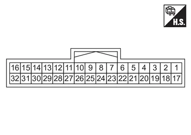
PHYSICAL VALUES
| Terminal No. (Wire color) | Description | Condition | Value | |||
|---|---|---|---|---|---|---|
| + | - | Signal name | Input / Output | |||
|
2 (LA/G) |
Ground | CAN-L | ŌĆö | ŌĆö | ŌĆö | ŌĆö |
|
3 (LA/R) |
CAN-L | ŌĆö | ŌĆö | ŌĆö | ŌĆö | |
|
4 (GR) |
CAN-H | ŌĆö | ŌĆö | ŌĆö | ŌĆö | |
|
5 (LA/R) |
Accessory power supply | Input | Auto ACC function ON | 6 - 16 V | ||
|
6 (GR) |
CAN-H | ŌĆö | ŌĆö | ŌĆö | ŌĆö | |
|
7 (LA/V) |
CAN-L | ŌĆö | ŌĆö | ŌĆö | ŌĆö | |
|
8 (LA/P) |
CAN-L | ŌĆö | ŌĆö | ŌĆö | ŌĆö | |
|
10 (GR) |
CAN-H | ŌĆö | ŌĆö | ŌĆö | ŌĆö | |
|
12 (BR) |
CAN-H | ŌĆö | ŌĆö | ŌĆö | ŌĆö | |
|
15 (LA/L) |
Ignition relay | Input | Ignition switch ON | Approx. 0 V | ||
|
16 (LA/G) |
Accessory relay | Input | Auto ACC function ON | Approx. 0 V | ||
|
17 (LA/Y) |
Battery power supply | Input | Always | 6 - 16 V | ||
|
18 (LA/GR) |
CAN-H | ŌĆö | ŌĆö | ŌĆö | ŌĆö | |
|
19 (LA/B) |
Ground | ŌĆö | Ignition switch ON | ŌĆö | Approx. 0 V | |
|
20 (LA/GR) |
CAN-H | ŌĆö | ŌĆö | ŌĆö | ŌĆö | |
|
21 (V) |
CAN-L | ŌĆö | ŌĆö | ŌĆö | ŌĆö | |
|
22 (G) |
CAN-L | ŌĆö | ŌĆö | ŌĆö | ŌĆö | |
|
23 (V) |
Automatic brake hold switch indicator | Output | Ignition switch ON | Automatic brake hold function ON | Approx. 4 V | |
| Automatic brake hold function OFF | Approx. 12 V | |||||
|
24 (LA/GR) |
CAN-H | ŌĆö | ŌĆö | ŌĆö | ŌĆö | |
|
25 (LA/GR) |
CAN-H | ŌĆö | ŌĆö | ŌĆö | ŌĆö | |
|
26 (P) |
CAN-L | ŌĆö | ŌĆö | ŌĆö | ŌĆö | |
|
28 (Y) |
CAN-L | ŌĆö | ŌĆö | ŌĆö | ŌĆö | |
|
29 (SB) |
Automatic brake hold switch | Input | Ignition switch ON | Automatic brake hold switch is pushing | Approx. 0 V | |
|
32 (LA/P) |
Stop lamp relay | Input | Ignition switch ON | Approx. 0 V | ||
Fail-safe
Refer to Fail-safe.
DTC Inspection Priority Chart
When multiple DTCs are displayed simultaneously, check them one by one according to the following priority list.
| Priority | Detected item (DTC) |
|---|---|
| 1 |
|
| 2 |
|
| 3 |
|
| 4 |
|
| 5 |
|
| 6 |
|
DTC Index
| DTC | Display item | Warning message | Refer to |
|---|---|---|---|
| C1B80-54 | Calibration not completed | ON | DTC Description |
| C1B81-55 | Configuration not completed | ON | DTC Description |
| C1B8B-82 | Power network separate relay | - | DTC Description |
| C1B8C-82 | Battery management system | - | DTC Description |
| C1B8D-82 | AVM | - | DTC Description |
| C1B8F-82 | IPDM E/R communication | ON | DTC Description |
| C1B90-82 | EPS | - | DTC Description |
| C1B92-82 | Brake control system | ON | DTC Description |
| C1B93-82 | Engine/HEV system | ON | DTC Description |
| C1B94-82 | TM system | ON | DTC Description |
| C1B96-82 | ADAS SYSTEM | - | DTC Description |
| C1B97-82 | BCM | ON | DTC Description |
| C1BB4-44 | Control module | ON | DTC Description |
| C1BB4-45 | Control module | ON* | DTC Description |
| C1BB4-46 | Control module | ON | DTC Description |
| C1BB4-49 | Control module | ON* | DTC Description |
| U0076-00 | Control module communication Bus D Off | - | DTC Description |
| U007A-00 | Control module communication Bus H Off | - | DTC Description |
| U1327-52 | MAC key update | - | DTC Description |
| U1327-54 | MAC key update | - | DTC Description |
| U2118-87 | CAN communication error (Intelligent Key unit) | OFF | DTC Description |
| U2140-57 | CAN communication error (ECM) | - | DTC Description |
| U2140-83 | CAN communication error (ECM) | ON | DTC Description |
| U2140-87 | CAN communication error (ECM) | ON | DTC Description |
| U2141-57 | CAN communication error (TCM) | - | DTC Description |
| U2143-83 | CAN communication error (VCM) | ON | DTC Description |
| U2143-87 | CAN communication error (VCM) | - | DTC Description |
| U214F-57 | CAN communication error (BCM) | - | DTC Description |
| U214F-83 | CAN communication error (BCM) | ON | DTC Description |
| U214F-87 | CAN communication error (BCM) | ON* | DTC Description |
| U2152-57 | CAN communication error (ADAS control unit) | - | DTC Description |
| U2152-83 | CAN communication error (ADAS control unit) | - | DTC Description |
| U2152-87 | CAN communication error (ADAS control unit) | - | DTC Description |
| U2154-87 | CAN communication error (AV control unit) | - | DTC Description |
| U215B-83 | CAN communication error (IPDM E/R) | ON | DTC Description |
| U215B-87 | CAN communication error (IPDM E/R) | ON | DTC Description |
| U2165-57 | CAN communication error (sonar control unit) | - | DTC Description |
| U218B-83 | CAN communication error [12V sub battery (Lithium ion battery)] | - | DTC Description |
| U218B-87 | CAN communication error [12V sub battery (Lithium ion battery)] | - | DTC Description |
| U2248-83 | CAN communication error [ABS actuator and electric unit (control unit)] | ON | DTC Description |
| U2248-87 | CAN communication error [ABS actuator and electric unit (control unit)] | ON | DTC Description |
| U2359-83 | CAN communication error (steering unit) | - | DTC Description |
| U2359-87 | CAN communication error (steering unit) | - | DTC Description |
| U2448-87 | CAN communication error [ABS actuator and electric unit (control unit)] | ON | DTC Description |
| U24A6-83 | CAN communication error (power network separate relay) | - | DTC Description |
| U24A6-87 | CAN communication error (power network separate relay) | - | DTC Description |
| U2541-83 | CAN communication error (TCM) | ON | DTC Description |
| U2541-87 | CAN communication error (TCM) | ON | DTC Description |
| U2675-83 | CAN communication error (around view monitor control unit) | - | DTC Description |
| U2675-87 | CAN communication error (around view monitor control unit) | - | DTC Description |
| U2A03-88 | Communication Bus Off CH-FD | - | DTC Description |
| U2A0A-88 | Communication Bus Off ITS6-FD | - | DTC Description |
| U2A0B-88 | Communication Bus Off CH2-CAN | - | DTC Description |
| U2A0E-88 | Communication Bus Off CH2-FD | - | DTC Description |
| U2A16-88 | CAN Bus Off 6 | - | DTC Description |
| U2A17-88 | CAN Bus Off 7 | - | DTC Description |
| U2E52-57 | CAN communication error (ADAS control unit) | - | DTC Description |
| U2E52-83 | CAN communication error (ADAS control unit) | - | DTC Description |
| U2E52-87 | CAN communication error (ADAS control unit) | - | DTC Description |
| U2E65-57 | CAN communication error (sonar control unit) | - | DTC Description |
| U2E75-57 | CAN communication error (around view monitor control unit) | - | DTC Description |
*: Chassis control warning in information display turns ON/OFF according to a condition when DTC is detected.
Other materials:
Adas Control Unit. Basic Inspection
Additional Service When Replacing Adas Control Unit 2
Without Propilot Assist 2.1
Work Procedure
Always perform the additional service after replacing the ADAS control unit 2.ADAS CONTROL UNIT 2 CONFIGURATION
Perform saving Nissan Ariya vehicle internal information according to "Replace ECU" i ...
Precaution. Precautions
Precaution for Supplemental Restraint System (SRS) "AIR BAG" and "SEAT BELT PRE-TENSIONER"
The Supplemental Restraint System such as ŌĆ£AIR BAGŌĆØ and ŌĆ£SEAT BELT
PRE-TENSIONERŌĆØ, used along with a front seat belt, helps to reduce the
risk or severity of injury to the driver and front passeng ...
U0079-00 Can Comm Circuit
DTC Description
DESCRIPTIONCAN (Controller Area Network) is a serial
communication line for real-time application. It is an onNissan Ariya
vehicle multiplex communication line with high data communication speed
and excellent error detection ability. Many electronic control units are
equippe ...