Nissan Rogue Service Manual: CAN system (type 2)
MAIN LINE BETWEEN IPDM-E AND DLC CIRCUIT
Diagnosis Procedure
1.CHECK CONNECTOR
- Turn the ignition switch OFF.
- Disconnect the battery cable from the negative terminal.
- Check the following terminals and connectors for damage, bend and loose connection (connector side and harness side).
- Harness connector E152
- Harness connector M31
Is the inspection result normal? YES >> GO TO 2.
NO >> Repair the terminal and connector.
2.CHECK HARNESS CONTINUITY (OPEN CIRCUIT)
- Disconnect the following harness connectors.
- IPDM E/R
- Harness connectors E152 and M31
- Check the continuity between the IPDM E/R harness connector and the harness connector.
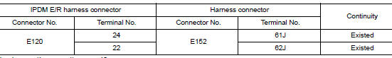
Is the inspection result normal? YES >> GO TO 3.
NO >> Repair the main line between the IPDM E/R and the harness connector E152.
3.CHECK HARNESS CONTINUITY (OPEN CIRCUIT)
Check the continuity between the harness connector and the data link connector.
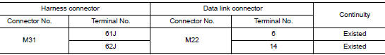
Is the inspection result normal? YES (Present error)>>Check CAN system type decision again.
YES (Past error)>>Error was detected in the main line between the IPDM E/R and the data link connector.
NO >> Repair the main line between the harness connector M31 and the data link connector.
MAIN LINE BETWEEN DLC AND CCM CIRCUIT
Diagnosis Procedure
1.CHECK HARNESS CONTINUITY (OPEN CIRCUIT)
- Turn the ignition switch OFF.
- Disconnect the battery cable from the negative terminal.
- Disconnect the following harness connectors.
- ECM
- Chassis control module
- Check the continuity between the data link connector and the chassis control module harness connector.
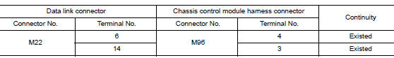
Is the inspection result normal? YES (Present error)>>Check CAN system type decision again.
YES (Past error)>>Error was detected in the main line between the data link connector and the chassis control module.
NO >> Repair the main line between the data link connector and the chassis control module.
MAIN LINE BETWEEN CCM AND PWBD CIRCUIT
Diagnosis Procedure
1.CHECK CONNECTOR
- Turn the ignition switch OFF.
- Disconnect the battery cable from the negative terminal.
- Check the following terminals and connectors for damage, bend and loose connection (connector side and harness side).
- Harness connector M69
- Harness connector B41
Is the inspection result normal? YES >> GO TO 2.
NO >> Repair the terminal and connector.
2.CHECK HARNESS CONTINUITY (OPEN CIRCUIT)
- Disconnect the following harness connectors.
- Chassis control module
- Harness connectors M69 and B41
- Check the continuity between the chassis control module harness connector and the harness connector.
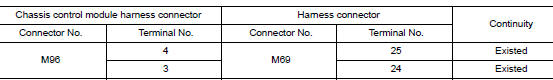
Is the inspection result normal? YES >> GO TO 3.
NO >> Repair the main line between the chassis control module and the harness connector M69.
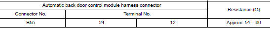
3.CHECK HARNESS CONTINUITY (OPEN CIRCUIT)
- Disconnect the connector of automatic back door control module.
- Check the continuity between the harness connector and the automatic back door control module harness connector.
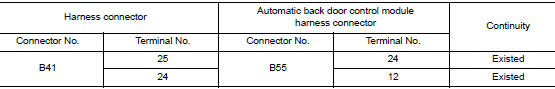
Is the inspection result normal? YES (Present error)>>Check CAN system type decision again.
YES (Past error)>>Error was detected in the main line between the chassis control module and the automatic back door control module.
NO >> Repair the main line between the harness connector B41 and the automatic back door control module.
ECM BRANCH LINE CIRCUIT
Diagnosis Procedure
1.CHECK CONNECTOR
- Turn the ignition switch OFF.
- Disconnect the battery cable from the negative terminal.
- Check the terminals and connectors of the ECM for damage, bend and loose connection (unit side and connector side).
Is the inspection result normal? YES >> GO TO 2.
NO >> Repair the terminal and connector.
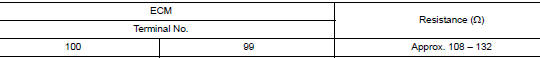
2.CHECK HARNESS FOR OPEN CIRCUIT
- Disconnect the connector of ECM.
- Check the resistance between the ECM harness connector terminals.
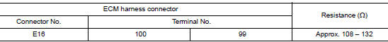
Is the measurement value within the specification? YES >> GO TO 3.
NO >> Repair the ECM branch line.
3.CHECK POWER SUPPLY AND GROUND CIRCUIT
Check the power supply and the ground circuit of the ECM. Refer to EC-165, "Diagnosis Procedure".
Is the inspection result normal? YES (Present error)>>Replace the ECM. Refer to EC-499, "Removal and Installation".
YES (Past error)>>Error was detected in the ECM branch line.
NO >> Repair the power supply and the ground circuit.
ABS BRANCH LINE CIRCUIT
Diagnosis Procedure
1.CHECK CONNECTOR
- Turn the ignition switch OFF.
- Disconnect the battery cable from the negative terminal.
- Check the terminals and connectors of the ABS actuator and electric unit (control unit) for damage, bend and loose connection (unit side and connector side).
Is the inspection result normal? YES >> GO TO 2.
NO >> Repair the terminal and connector.
2.CHECK HARNESS FOR OPEN CIRCUIT
- Disconnect the connector of ABS actuator and electric unit (control unit).
- Check the resistance between the ABS actuator and electric unit (control unit) harness connector terminals.
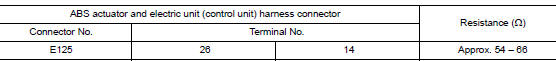
Is the measurement value within the specification? YES >> GO TO 3.
NO >> Repair the ABS actuator and electric unit (control unit) branch line.
3.CHECK POWER SUPPLY AND GROUND CIRCUIT
Check the power supply and the ground circuit of the ABS actuator and electric unit (control unit). Refer to BRC-114, "Diagnosis Procedure".
Is the inspection result normal? YES (Present error)>>Replace the ABS actuator and electric unit (control unit). Refer to BRC-136, "Removal and Installation".
YES (Past error)>>Error was detected in the ABS actuator and electric unit (control unit) branch line.
NO >> Repair the power supply and the ground circuit.
IPDM-E BRANCH LINE CIRCUIT
Diagnosis Procedure
1.CHECK CONNECTOR
- Turn the ignition switch OFF.
- Disconnect the battery cable from the negative terminal.
- Check the terminals and connectors of the IPDM E/R for damage, bend and loose connection (unit side and connector side).
Is the inspection result normal? YES >> GO TO 2.
NO >> Repair the terminal and connector.
2.CHECK HARNESS FOR OPEN CIRCUIT
- Disconnect the connector of IPDM E/R.
- Check the resistance between the IPDM E/R harness connector terminals.
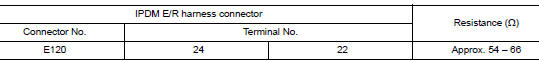
Is the measurement value within the specification? YES >> GO TO 3.
NO >> Repair the IPDM E/R branch line.
3.CHECK POWER SUPPLY AND GROUND CIRCUIT
Check the power supply and the ground circuit of the IPDM E/R. Refer to PCS-34, "Diagnosis Procedure".
Is the inspection result normal? YES (Present error)>>Replace the IPDM E/R. Refer to PCS-35, "Removal and Installation".
YES (Past error)>>Error was detected in the IPDM E/R branch line.
NO >> Repair the power supply and the ground circuit.
TCM BRANCH LINE CIRCUIT
Diagnosis Procedure
1.CHECK CONNECTOR
- Turn the ignition switch OFF.
- Disconnect the battery cable from the negative terminal.
- Check the following terminals and connectors for damage, bend and loose connection (unit side and connector side).
- TCM
- IPDM E/R
Is the inspection result normal? YES >> GO TO 2.
NO >> Repair the terminal and connector.
2.CHECK HARNESS CONTINUITY (OPEN CIRCUIT)
- Disconnect the following harness connectors.
- TCM
- IPDM E/R
- Check the continuity between the TCM harness connector and the IPDM E/R harness connector.
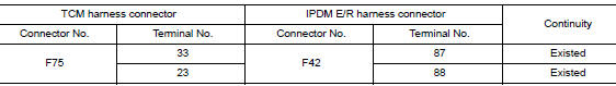
Is the inspection result normal? YES >> GO TO 3.
NO >> Repair the branch line between the TCM and IPDM E/R.
3.CHECK IPDM E/R (OPEN CIRCUIT)
Check the continuity between the IPDM E/R terminals.
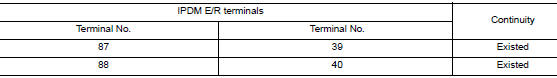
Is the inspection result normal? YES >> GO TO 4.
NO >> Replace the IPDM E/R.
4.CHECK HARNESS FOR OPEN CIRCUIT
Check the resistance between the IPDM E/R harness connector terminals.
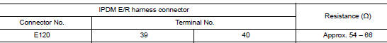
Is the measurement value within the specification? YES >> GO TO 5.
NO >> Repair the IPDM E/R branch line.
5.CHECK POWER SUPPLY AND GROUND CIRCUIT
Check the power supply and the ground circuit of the TCM. Refer to TM-176, "Diagnosis Procedure".
Is the inspection result normal? YES (Present error)>>Replace the TCM. Refer to TM-202, "Removal and Installation".
YES (Past error)>>Error was detected in the TCM branch line.
NO >> Repair the power supply and the ground circuit.
DLC BRANCH LINE CIRCUIT
Diagnosis Procedure
1.CHECK CONNECTOR
- Turn the ignition switch OFF.
- Disconnect the battery cable from the negative terminal.
- Check the terminals and connectors of the data link connector for damage, bend and loose connection (connector side and harness side).
Is the inspection result normal? YES >> GO TO 2.
NO >> Repair the terminal and connector.
2.CHECK HARNESS FOR OPEN CIRCUIT
Check the resistance between the data link connector terminals.
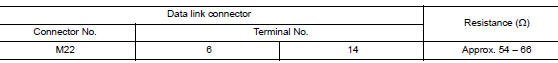
Is the measurement value within the specification? YES (Present error)>>Check CAN system type decision again.
YES (Past error)>>Error was detected in the data link connector branch line circuit.
NO >> Repair the data link connector branch line.
EPS BRANCH LINE CIRCUIT
Diagnosis Procedure
1.CHECK CONNECTOR
- Turn the ignition switch OFF.
- Disconnect the battery cable from the negative terminal.
- Check the terminals and connectors of the EPS control unit for damage, bend and loose connection (unit side and connector side).
Is the inspection result normal? YES >> GO TO 2.
NO >> Repair the terminal and connector.
2.CHECK HARNESS FOR OPEN CIRCUIT
- Disconnect the connector of EPS control unit.
- Check the resistance between the EPS control unit harness connector terminals.
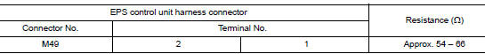
Is the measurement value within the specification? YES >> GO TO 3.
NO >> Repair the EPS control unit branch line.
3.CHECK POWER SUPPLY AND GROUND CIRCUIT
Check the power supply and the ground circuit of the EPS control unit. Refer to STC-20, "Diagnosis Procedure".
Is the inspection result normal? YES (Present error)>>Replace the EPS control unit. Refer to STC-36, "Removal and Installation".
YES (Past error)>>Error was detected in the EPS control unit branch line.
NO >> Repair the power supply and the ground circuit.
M&A BRANCH LINE CIRCUIT
Diagnosis Procedure
1.CHECK CONNECTOR
- Turn the ignition switch OFF.
- Disconnect the battery cable from the negative terminal.
- Check the terminals and connectors of the combination meter for damage, bend and loose connection (unit side and connector side).
Is the inspection result normal? YES >> GO TO 2.
NO >> Repair the terminal and connector.
2.CHECK HARNESS FOR OPEN CIRCUIT
- Disconnect the connector of combination meter.
- Check the resistance between the combination meter harness connector terminals.
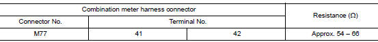
Is the measurement value within the specification? YES >> GO TO 3.
NO >> Repair the combination meter branch line.
3.CHECK POWER SUPPLY AND GROUND CIRCUIT
Check the power supply and the ground circuit of the combination meter. Refer to MWI-59, "COMBINATION METER : Diagnosis Procedure".
Is the inspection result normal? YES (Present error)>>Replace the combination meter. Refer to MWI-82, "Removal and Installation".
YES (Past error)>>Error was detected in the combination meter branch line.
NO >> Repair the power supply and the ground circuit.
STRG BRANCH LINE CIRCUIT
Diagnosis Procedure
1.CHECK CONNECTOR
- Turn the ignition switch OFF.
- Disconnect the battery cable from the negative terminal.
- Check the terminals and connectors of the steering angle sensor for damage, bend and loose connection (unit side and connector side).
Is the inspection result normal? YES >> GO TO 2.
NO >> Repair the terminal and connector.
2.CHECK HARNESS FOR OPEN CIRCUIT
- Disconnect the connector of steering angle sensor.
- Check the resistance between the steering angle sensor harness connector terminals.
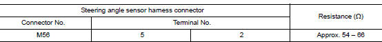
Is the measurement value within the specification? YES >> GO TO 3.
NO >> Repair the steering angle sensor branch line.
3.CHECK POWER SUPPLY AND GROUND CIRCUIT
Check the power supply and the ground circuit of the steering angle sensor. Refer to BRC-57, "Wiring Diagram".
Is the inspection result normal? YES (Present error)>>Replace the steering angle sensor. Refer to BRC-139, "Removal and Installation".
YES (Past error)>>Error was detected in the steering angle sensor branch line.
NO >> Repair the power supply and the ground circuit.
A-BAG BRANCH LINE CIRCUIT
Diagnosis Procedure
WARNING:
- Before servicing, turn ignition switch OFF, disconnect battery negative terminal, and wait 3 minutes or more. (To discharge backup capacitor.)
- Never use unspecified tester or other measuring device.
1.CHECK CONNECTOR
- Turn the ignition switch OFF.
- Disconnect the battery cable from the negative terminal.
- Check the terminals and connectors of the air bag diagnosis sensor unit for damage, bend and loose connection (unit side and connector side).
Is the inspection result normal? YES >> GO TO 2.
NO >> Replace the main harness.
2.CHECK AIR BAG DIAGNOSIS SENSOR UNIT
Check the air bag diagnosis sensor unit. Refer to SRC-39, "Work Flow".
Is the inspection result normal? YES >> Replace the main harness.
NO >> Replace parts whose air bag system has a malfunction.
CCM BRANCH LINE CIRCUIT
Diagnosis Procedure
1.CHECK CONNECTOR
- Turn the ignition switch OFF.
- Disconnect the battery cable from the negative terminal.
- Check the terminals and connectors of the chassis control module connector for damage, bend and loose connection (unit side and connector side).
Is the inspection result normal? YES >> GO TO 2.
NO >> Repair the terminal and connector.
2.CHECK HARNESS FOR OPEN CIRCUIT
- Disconnect the connector of chassis control module.
- Check the resistance between the chassis control module harness connector terminals.
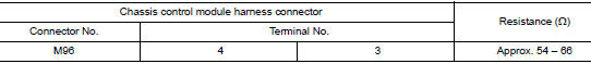
Is the measurement value within the specification? YES >> GO TO 3.
NO >> Repair the chassis control module branch line.
3.CHECK POWER SUPPLY AND GROUND CIRCUIT
Check the power supply and the ground circuit of the chassis control module. Refer to DAS-272, "Diagnosis Procedure".
Is the inspection result normal? YES (Present error)>>Replace the chassis control module. Refer to DAS-277, "Removal and Installation".
YES (Past error)>>Error was detected in the chassis control module branch line.
NG >> Repair the power supply and the ground circuit.
PWBD BRANCH LINE CIRCUIT
Diagnosis Procedure
1.CHECK CONNECTOR
- Turn the ignition switch OFF.
- Disconnect the battery cable from the negative terminal.
- Check the terminals and connectors of the automatic back door control module for damage, bend and loose connection (unit side and connector side).
Is the inspection result normal? YES >> GO TO 2.
NO >> Repair the terminal and connector.
2.CHECK HARNESS FOR OPEN CIRCUIT
- Disconnect the connector of automatic back door control module.
- Check the resistance between the automatic back door control module harness connector terminals.
Is the measurement value within the specification? YES >> GO TO 3.
NO >> Repair the automatic back door control module branch line.
3.CHECK POWER SUPPLY AND GROUND CIRCUIT
Check the power supply and the ground circuit of the automatic back door control module. Refer to DLK-141, "AUTOMATIC BACK DOOR CONTROL UNIT : Diagnosis Procedure".
Is the inspection result normal? YES (Present error)>>Replace the automatic back door control module. Refer to DLK-276, "Removal and Installation".
YES (Past error)>>Error was detected in the automatic back door control module branch line.
NG >> Repair the power supply and the ground circuit.
BCM BRANCH LINE CIRCUIT
Diagnosis Procedure
1.CHECK CONNECTOR
- Turn the ignition switch OFF.
- Disconnect the battery cable from the negative terminal.
- Check the terminals and connectors of the BCM for damage, bend and loose connection (unit side and connector side).
Is the inspection result normal? YES >> GO TO 2.
NO >> Repair the terminal and connector.
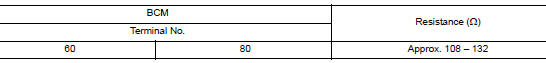
2.CHECK HARNESS FOR OPEN CIRCUIT
- Disconnect the connector of BCM.
- Check the resistance between the BCM harness connector terminals.
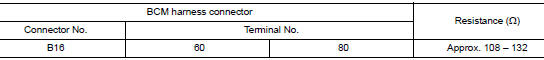
Is the measurement value within the specification? YES >> GO TO 3.
NO >> Repair the BCM branch line.
3.CHECK POWER SUPPLY AND GROUND CIRCUIT
Check the power supply and the ground circuit of the BCM. Refer to the following.
- With intelligent key system: BCS-68, "Diagnosis Procedure".
- Without intelligent key system: BCS-128, "Diagnosis Procedure".
Is the inspection result normal? YES (Present error)>>Replace the BCM. Refer to the following.
- With intelligent key system: BCS-75, "Removal and Installation".
- Without intelligent key system: BCS-135, "Removal and Installation".
YES (Past error)>>Error was detected in the BCM branch line.
NO >> Repair the power supply and the ground circuit.
HVAC BRANCH LINE CIRCUIT
Diagnosis Procedure
1.CHECK CONNECTOR
- Turn the ignition switch OFF.
- Disconnect the battery cable from the negative terminal.
- Check the following terminals and connectors for damage, bend and loose connection (unit side and connector side).
- A/C auto amp. (With auto A/C)
- Harness connector M127 (With auto A/C)
- Harness connector M125 (With auto A/C)
- Front air control (Without auto A/C)
- BCM
Is the inspection result normal? YES >> GO TO 2. (With auto A/C) YES >> GO TO 3. (Without auto A/C) NO >> Repair the terminal and connector.
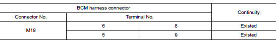
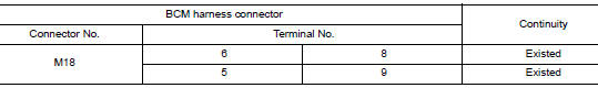
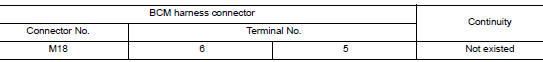
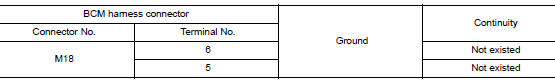
2.CHECK HARNESS CONTINUITY (OPEN CIRCUIT)
- Disconnect the connector of BCM.
- Check the continuity between the BCM harness connector terminals.
Is the inspection result normal? YES >> GO TO 3.
NO >> Check the harness and repair the root cause (CAN communication circuit 2 side). Refer to LAN- 265, "Diagnosis Procedure".
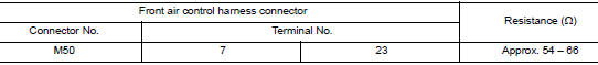
3.CHECK HARNESS FOR OPEN CIRCUIT
- Connect the connector of BCM (With auto A/C).
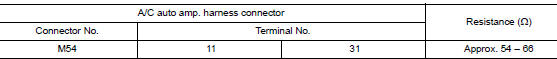
- Disconnect the connector of A/C auto amp. (With auto A/C) or front air control (Without auto A/C).
- Check the resistance between the A/C auto amp. (With auto A/C) or front air control (Without auto A/C) harness connector terminals.
- With auto A/C
- Without auto A/C
Is the measurement value within the specification? YES >> GO TO 4.
NO >> Repair the A/C auto amp. (With auto A/C) or front air control (Without auto A/C) branch line.
4.CHECK POWER SUPPLY AND GROUND CIRCUIT
Check the power supply and the ground circuit of the A/C auto amp. (With auto A/C) or front air control (Without auto A/C). Refer to the following.
- Automatic air conditioning: HAC-56, "Diagnosis Procedure".
- Manual air conditioning: HAC-166, "FRONT A/C CONTROL : Diagnosis Procedure".
Is the inspection result normal? YES (Present error)>>Replace the A/C auto amp. (With auto A/C) or front air control (Without auto A/C).
Refer to the following.
- Automatic air conditioning: HAC-103, "Removal and Installation".
- Manual air conditioning: HAC-181, "Removal and Installation".
YES (Past error)>>Error was detected in the A/C auto amp. (With auto A/C) or front air control (Without auto A/C) branch line.
NO >> Repair the power supply and the ground circuit.
CAN COMMUNICATION CIRCUIT 1
Diagnosis Procedure
1.CONNECTOR INSPECTION
- Turn the ignition switch OFF.
- Disconnect the battery cable from the negative terminal.
- Disconnect all the unit connectors on CAN communication circuit 1.
- Check terminals and connectors for damage, bend and loose connection.
Is the inspection result normal? YES >> GO TO 2.
NO >> Repair the terminal and connector.
2.CHECK HARNESS CONTINUITY (SHORT CIRCUIT)
Check the continuity between the data link connector terminals.
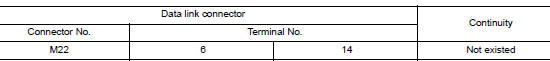
Is the inspection result normal? YES >> GO TO 3.
NO >> Check the harness and repair or replace (if shield line or fuse block (J/B) is short) the root cause.
3.CHECK HARNESS CONTINUITY (SHORT CIRCUIT)
Check the continuity between the data link connector and the ground.
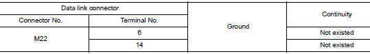
Is the inspection result normal? YES >> GO TO 4.
NO >> Check the harness and repair or replace (if shield line or fuse block (J/B) is short) the root cause.
4.CHECK ECM AND BCM TERMINATION CIRCUIT
- Remove the ECM and the BCM.
- Check the resistance between the IPDM E/R terminals.
- Check the resistance between the BCM terminals.
Is the measurement value within the specification? YES >> GO TO 5.
NO >> Replace the ECM and/or the BCM.
5.CHECK SYMPTOM
Connect all the connectors. Check if the symptoms described in the “Symptom (Results from interview with customer)” are reproduced.
Inspection result Reproduced>>GO TO 6.
Non-reproduced>>Start the diagnosis again. Follow the trouble diagnosis procedure when past error is detected.
6.CHECK UNIT REPRODUCTION
Perform the reproduction test as per the following procedure for each unit.
- Turn the ignition switch OFF.
- Disconnect the battery cable from the negative terminal.
- Disconnect one of the unit connectors of CAN communication circuit
1.
NOTE: ECM and BCM have a termination circuit. Check other units first.
- Connect the battery cable to the negative terminal. Check if the
symptoms described in the “Symptom
(Results from interview with customer)” are reproduced.
NOTE: Although unit-related error symptoms occur, do not confuse them with other symptoms.
Inspection result
Reproduced>>Connect the connector. Check other units as per the above procedure.
Non-reproduced>>Replace the unit whose connector was disconnected.
CAN COMMUNICATION CIRCUIT 2
Diagnosis Procedure
1.CONNECTOR INSPECTION
- Turn the ignition switch OFF.
- Disconnect the battery cable from the negative terminal.
- Check the terminals and connectors of the BCM for damage, bend and loose connection (unit side and connector side).
Is the inspection result normal? YES >> GO TO 2.
NO >> Repair the terminal and connector.
2.CHECK HARNESS CONTINUITY (OPEN CIRCUIT)
- Disconnect the connector of BCM.
- Check the continuity between the BCM harness connector terminals.
Is the inspection result normal? YES >> GO TO 3.
NO >> Check the harness and repair or replace the root cause.
3.CHECK HARNESS CONTINUITY (SHORT CIRCUIT)
- Disconnect all the unit connectors on CAN communication circuit 2.
- Check the continuity between the BCM harness connector terminals.
Is the inspection result normal? YES >> GO TO 4.
NO >> Check the harness and repair or replace the root cause.
4.CHECK HARNESS CONTINUITY (SHORT CIRCUIT)
Check the continuity between the BCM and the ground.
Is the inspection result normal? YES >> GO TO 5.
NO >> Check the harness and repair or replace (if shield line is short) the root cause.
5.CHECK BCM TERMINATION CIRCUIT
- Remove the BCM.
- Check the resistance between the BCM terminals.


Is the measurement value within the specification? YES >> GO TO 6.
NO >> Replace the chassis control module.
6.CHECK SYMPTOM
Connect all the connectors. Check if the symptoms described in the “Symptom (Results from interview with customer)” are reproduced.
Inspection result Reproduced>>GO TO 7.
Non-reproduced>>Start the diagnosis again. Follow the trouble diagnosis procedure when past error is detected.
7.CHECK UNIT REPRODUCTION
Perform the reproduction test as per the following procedure for each unit.
- Turn the ignition switch OFF.
- Disconnect the battery cable from the negative terminal.
- Disconnect one of the unit connectors of CAN communication circuit
2.
NOTE: BCM has two termination circuits. Check other units first.
- Connect the battery cable to the negative terminal. Check if the
symptoms described in the “Symptom
(Results from interview with customer)” are reproduced.
NOTE: Although unit-related error symptoms occur, do not confuse them with other symptoms.
Inspection result
Reproduced>>Connect the connector. Check other units as per the above procedure.
Non-reproduced>>Replace the unit whose connector was disconnected.
 CAN system (type 1)
DTC/CIRCUIT DIAGNOSIS
MAIN LINE BETWEEN IPDM-E AND DLC CIRCUIT
Diagnosis Procedure
1.CHECK CONNECTOR
Turn the ignition switch OFF.
Disconnect the battery cable from the negative t ...
 CAN system (type 3)
MAIN LINE BETWEEN IPDM-E AND DLC CIRCUIT
Diagnosis Procedure
1.CHECK CONNECTOR
Turn the ignition switch OFF.
Disconnect the battery cable from the negative terminal.
Check the fo ...
Other materials:
Flat towing for front wheel drive vehicle
(if so equipped)
Towing your vehicle with all four wheels on the
ground is sometimes called flat towing. This
method is sometimes used when towing a vehicle
behind a recreational vehicle, such as a motor
home.
CAUTION
Failure to follow these guidelines can
result in severe transmission dama ...
NISSAN Intelligent Key® (if so equipped)
Replace the battery in the Intelligent Key as follows:
Remove the mechanical key from the Intelligent
Key.
Insert a small screwdriver A into the slit B
of the corner and twist it to separate the
upper part from the lower part. Use a cloth to
protect the casing.
Replace th ...
P0743 torque converter
DTC Description
DTC DETECTION LOGIC
DTC
CONSULT screen terms
(Trouble diagnosis content)
DTC detection condition
P0743
TORQUE CONVERTER
(Torque Converter Clutch Circuit Electrical)
When all of the following conditions are satisfied and this state is
maintained ...
