Nissan Rogue Service Manual: C1164, C1165 CV system
DTC Logic
DTC Logic
| DTC | Display Item | Malfunction detected condition | Possible causes |
| C1164 | CV 1 | When a malfunction is detected in cut valve 1. |
|
| C1165 | CV 2 | When a malfunction is detected in cut valve 2. |
DTC CONFIRMATION PROCEDURE
1.CHECK SELF-DIAGNOSTIC RESULT
 With CONSULT.
- Turn ignition switch ON.
- Perform self-diagnostic result.
Is DTC “C1164” or “C1165” detected? YES >> Proceed to diagnosis procedure. Refer to BRC-102, "Diagnosis Procedure".
NO >> Inspection End.
Diagnosis Procedure
Regarding Wiring Diagram information, refer to BRC-57, "Wiring Diagram".
1.CONNECTOR INSPECTION
- Turn ignition switch OFF.
- Disconnect ABS actuator and electric unit (control unit) connectors.
- Check connectors and terminals for deformation, disconnection, looseness or damage.
Is the inspection result normal? YES >> GO TO 2.
NO >> Repair or replace as necessary.
2.CHECK ABS ACTUATOR AND ELECTRIC UNIT (CONTROL UNIT) BATTERY POWER SUPPLY
Check voltage between ABS actuator and electric unit (control unit) connector E125 terminals 1, 25 and ground.
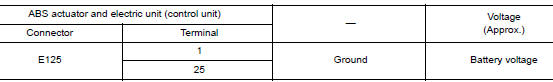
Is the inspection result normal? YES >> GO TO 3.
NO >> Repair or replace malfunctioning components.
3.CHECK ABS ACTUATOR AND ELECTRIC UNIT (CONTROL UNIT) GROUND CIRCUIT
Check continuity between ABS actuator and electric unit (control unit) connector E125 terminals 13, 38 and ground.
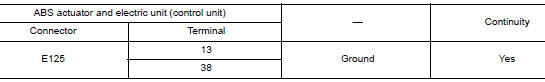
Is the inspection result normal? YES >> Replace ABS actuator and electric unit (control unit). Refer to BRC-136, "Removal and Installation".
NO >> Repair or replace malfunctioning components.
 C1160 DECEL G SEN SET
DTC Logic
DTC DETECTION LOGIC
DTC
Display Item
Malfunction detected condition
Possible causes
C1160
DECEL G SEN SET
When calibration of yaw rate/side/decel G sensor is ...
 C1170 variant coding
DTC Logic
DTC DETECTION LOGIC
DTC
Display Item
Malfunction detected condition
Possible causes
C1170
VARIANT CODING
When the information in ABS actuator and electric
...
Other materials:
Driver side door mirror defogger
Description
Heats the heating wire with the power supply from the rear window defogger
relay to prevent the door mirror
from fogging up.
Component Function Check
1. CHECK DOOR MIRROR DEFOGGER LH
Check that heating wire of door mirror defogger LH is heated when turning the
rear window defogg ...
Parking brake shoe
Exploded View
Back plate
Parking brake shoe
Brake strut
Return spring
Spring
Return spring to brake strut
Adjuster
Toggle lever
Anti-rattle pin
: Apply PBC (Poly Butyl
Cuprysil) grease or silicone-based grease
Removal and Installation
REMOVAL
WARNING ...
P1572 brake pedal position switch
DTC Description
DTC DETECTION LOGIC
NOTE:
This self-diagnosis has the one trip detection logic. When malfunction A is
detected, DTC is not stored
in ECM memory. And in that case, 1st trip DTC and 1st trip freeze frame data are
displayed. 1st trip
DTC is erased when ignition switch OFF. And ...
