Nissan Rogue Owners Manual: BSW system operation
BSW system operation
The BSW system operates above approximately 20 MPH (32 km/h).
When the camera unit detects vehicles in the detection zone, the Blind Spot indicator light located inside the outside mirrors will illuminate. If the turn signal is then activated, the system chimes (twice) and the Blind Spot indicator light flashes to alert the driver.
The Blind Spot indicator light continues to flash until the detected vehicle(s) leave the detection zone.
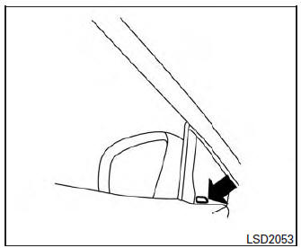
Blind Spot indicator light
Detection zone
The camera unit can detect vehicles on either side of your vehicle when part of another vehicle is within the detection zone shown as illustrated.
This detection zone typically starts from the outside mirror of your vehicle and extends approximately 10 ft (3.0 m) behind the rear bumper, and approximately 10 ft (3.0 m) sideways.
NOTE: The Blind Spot indicator lights will illuminate for a few seconds when the ignition switch is placed in the ON position. The brightness of the Blind Spot indicator lights is adjusted automatically depending on the brightness of the ambient light.
A chime sounds if the camera unit has already detected vehicles when the driver activates the turn signal. If a vehicle comes into the detection zone after the driver activates the turn signal, then only the Blind Spot indicator light flashes and no chime sounds. For additional information, refer to “BSW driving situations” in this section.
Turning on or off the BSW system
The BSW system is turned on or off using the settings menu in the vehicle information display.
SYSTEM ON: The BSW indicator in the vehicle information display will appear.
SYSTEM OFF: The BSW indicator in the vehicle information display will disappear.
Perform the following steps to enable or disable the BSW system:
- Press the
 button
until “Settings” displays
in the vehicle information display. Use
the t
button
until “Settings” displays
in the vehicle information display. Use
the t o select “Driver
Assistance”.
o select “Driver
Assistance”.Then press the ENTER button.
- Select “Driving Aids”, and press the ENTER button.
- To set the BSW system to on or off, use
the
 buttons to navigate in the
menu
and use the ENTER button to select or
change an item:
buttons to navigate in the
menu
and use the ENTER button to select or
change an item:
- Select “Blind Spot” and press the ENTER button.
- To turn on the warning, use the ENTER button to check box for “Warning (BSW)”
WARNING
|
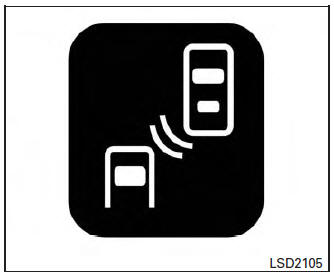
 Blind Spot Warning (BSW) System / Lane
Departure Warning (LDW) System (if so equipped)
Blind Spot Warning (BSW) System / Lane
Departure Warning (LDW) System (if so equipped)
The Blind Spot Warning (BSW) system helps
alert the driver of other vehicles in adjacent lanes
when changing lanes.
The Lane Departure Warning (LDW) system
helps alert the driver when the vehicl ...
 BSW driving situations
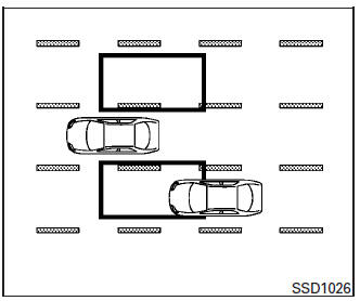
Another vehicle approaching from behind
The Blind Spot indicator light illuminates if a
vehicle enters the detection zone from behind in
an adjacent lane.
However, if the overtaking vehicle ...
Other materials:
Diagnosis system (BCM) (with intelligent key system)
COMMON ITEM
COMMON ITEM : CONSULT Function (BCM - COMMON ITEM)
APPLICATION ITEM
CONSULT performs the following functions via CAN communication with BCM.
Direct Diagnostic Mode
Description
Ecu Identification
The BCM part number is displayed.
Self Diagnostic ...
Drive belt
QR25DE engine
Crankshaft pulley
Drive belt automatic tensioner pulley
Water pump pulley
Generator pulley
Air conditioner pulley
WARNINGBe sure the ignition switch is placed in the
OFF or LOCK position before servicing
drive belt. The engine cou ...
Removal and installation
ACCELERATOR PEDAL ASSEMBLY
Exploded View
Brake pedal
Accelerator pedal assembly
Locator hook
Locator pin
Bolt
Removal and Installation
REMOVAL
Disconnect the harness connector from the accelerator pedal
assembly.
Remove the bolts, then rem ...
