Nissan Rogue Service Manual: Basic inspection
SERVICE INFORMATION FOR ELECTRICAL INCIDENT
Work flow
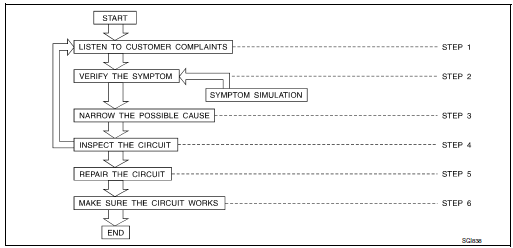
| STEP | DESCRIPTION | |
| STEP 1 | Get detailed information about the conditions and the
environment when the incident occurred.
The following are key pieces of information required to make a good analysis: |
|
| WHAT | Vehicle Model, Engine, Transmission/Transaxle and the System (i.e. Radio). | |
| WHEN | Date, Time of Day, Weather Conditions, Frequency. | |
| WHERE | Road Conditions, Altitude and Traffic Situation | |
| HOW | System Symptoms, Operating Conditions (Other Components
Interaction).
Service History and if any After Market Accessories have been installed. |
|
| STEP 2 | Operate the system, road test if necessary.
Verify the parameter of the incident. If the problem cannot be duplicated, refer to ŌĆ£Incident Simulation TestsŌĆØ. |
|
| STEP 3 | Get the proper diagnosis materials together including:
Identify where to begin diagnosis based upon your knowledge of the system operation and the customer comments. |
|
| STEP 4 | Inspect the system for mechanical binding, loose
connectors or wiring damage.
Determine which circuits and components are involved and diagnose using the Power Supply Routing and Harness Layouts. |
|
| STEP 5 | Repair or replace the incident circuit or component. | |
| STEP 6 | Operate the system in all modes. Verify the system works properly under all conditions. Make sure you have not inadvertently created a new incident during your diagnosis or repair steps. | |
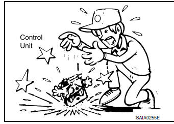
Control units and electrical parts
PRECAUTIONS
- Never reverse polarity of battery terminals.
- Install only parts specified for a vehicle.
- Before replacing the control unit, check the input and output and functions of the component parts.
- Do not apply excessive force when disconnecting a connector.
- Do not apply excessive shock to the control unit by dropping or hitting it.
- Be careful to prevent condensation in the control unit due to rapid temperature changes and do not let water or rain get on it. If water is found in the control unit, dry it fully and then install it in the vehicle.
- Be careful not to let oil to get on the control unit connector.
- Avoid cleaning the control unit with volatile oil.
- Do not disassemble the control unit, and do not remove the upper and lower covers.
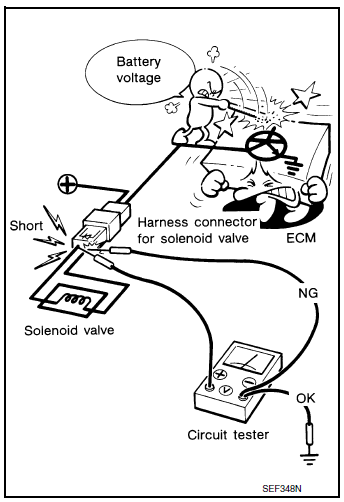
- When using a DMM, be careful not to let test probes get close to each other to prevent the power transistor in the control unit from damaging battery voltage because of short circuiting.
- When checking input and output signals of the control unit, use the specified check adapter.
 Vehicle information
Identification information
Model Variation
FWD Model
AWD Model
Prefix and Suffix Designations
Identification Number
Air conditioner specification label
Emission co ...
 How to check terminal
CONNECTOR AND TERMINAL PIN KIT
Use the connector and terminal pin kits listed below when
replacing connectors or terminals.
The connector and terminal pin kits contain some of the ...
Other materials:
Brake pedal vibration or operation sound occurs
Description
Brake pedal vibrates and motor sound from ABS actuator and electric unit
(control unit) occurs, when the
engine starts.
Brake pedal vibrates during braking.
CAUTION:
Vibration may be felt during brake pedal is lightly depressed (just placing a
foot on it) in the fo ...
B2205 vehicle speed
Description
Vehicle speed signal is transmitted from ABS actuator and electric unit
(control unit) via CAN communication
line to combination meter.
DTC Logic
DTC DETECTION LOGIC
DTC
CONSULT
Detection Condition
Possible Cause
B2205
VEHICLE SPEED CIRC ...
Cruise control operations
The cruise control allows driving at a speed between
25 - 89 MPH (40 - 144 km/h) without
keeping your foot on the accelerator pedal.
To turn on the cruise control, push the
ON┬ĘOFF switch ON. The CRUISE indicator light
in the vehicle information display will illuminate.
To set cruising spe ...
