Nissan Rogue Service Manual: Consult/gst checking system
Description
NOTE: This vehicle is diagnosed using the CONSULT-III plus.
- When CONSULT is connected with a data link connector equipped on the vehicle side, it will communicate with the control unit equipped in the vehicle and then enable various kinds of diagnostic tests.
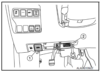
- Hood release handle
- Data link connector
- Refer to “CONSULT-III plus Operation Manual” for more information.
Function and System Application
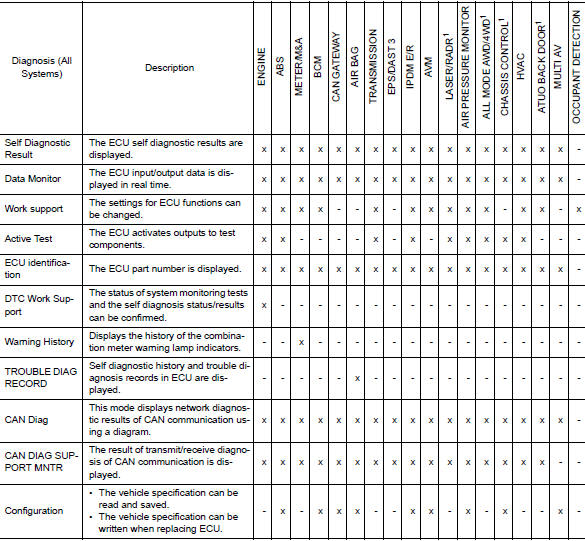
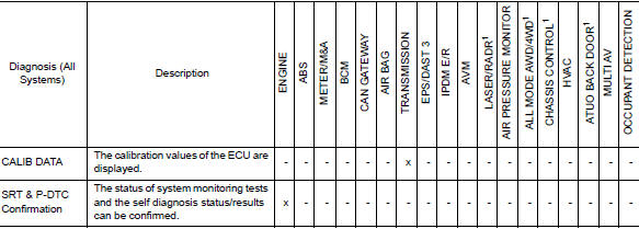
x: Applicable
1: If equipped
CONSULT Data Link Connector (DLC) Circuit
INSPECTION PROCEDURE
If the CONSULT cannot diagnose the system properly, check the following items.
| Symptom | Check item |
| CONSULT cannot access any system. |
|
| CONSULT cannot access individual system. (Other systems can be accessed.) |
|
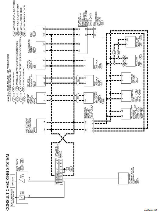
NOTE: The DDL2 circuits and CAN communication lines from DLC pins 6, 7 and 14 may be connected to more than one system. A short in a DDL circuit or CAN lines connected to a control unit in one system may affect CONSULT access to other systems. For a complete DDL circuit layout, refer to GI-51, "Wiring Diagram - CONSULT/ GST CHECKING SYSTEM". For a complete CAN line layout, refer to LAN-35, "Wiring Diagram - CAN SYSTEM -".
Wiring Diagram - CONSULT/GST CHECKING SYSTEM
 Circuit inspection
DESCRIPTION
In general, testing electrical circuits is an easy task if it is
approached in a logical and organized method.
Before beginning it is important to have all available informa ...
 Engine
...
Other materials:
Power window relay
Description
Power is supplied to the main power window and door lock/unlock with BCM
control.
Component Function Check
1. CHECK POWER WINDOW RELAY POWER SUPPLY CIRCUIT
Check that an operation noise of power window relay [located behind the A/C
switch assembly (automatic A/
C) or Front air c ...
Removal and installation
GENERATOR
Exploded View
REMOVAL
Cylinder head
Generator bracket
Washer
Generator
Water pump
Cylinder block
Removal and Installation
REMOVAL
Disconnect negative terminal from battery. Refer to PG-75,
"Exploded View".
Remove wheel and tire ...
Both doors mirror defogger don’t operate but rear window defogger operates
Diagnosis Procedure
Regarding Wiring Diagram information, refer to DEF-12, "Wiring Diagram".
1. CHECK DOOR MIRROR DEFOGGER FUSE
Check if the following fuse in fuse block (J/B) is blown.
Is the inspection result normal?
YES >> GO TO 2.
NO >> Replace the blown fuse af ...
