Nissan Rogue Service Manual: Basic inspection
DIAGNOSIS AND REPAIR WORK FLOW
Work Flow
DETAILED FLOW
1.INTERVIEW FROM THE CUSTOMER
Clarify customer complaints before inspection. First of all, perform an interview utilizing DAS-202, "Diagnostic Work Sheet" and reproduce the symptom as well as fully understand it. Ask customer about his/her complaints carefully. Check symptoms by driving vehicle with customer, if necessary.
CAUTION: Customers are not professional. Never guess easily like ‚Äúmaybe the customer means that...,‚ÄĚ or ‚Äúmaybe the customer mentions this symptom‚ÄĚ.
>> GO TO 2.
2.CHECK SYMPTOM
Reproduce the symptom that is indicated by the customer, based on the information from the customer obtained by the interview. Also check that the symptom is not caused by fail-safe mode. Refer to DAS-191, "Fail-Safe (Chassis Control Module)".
CAUTION: When the symptom is caused by normal operation, fully inspect each portion and obtain the understanding of customer that the symptom is not caused by a malfunction. >> GO TO 3.
3.PERFORM SELF-DIAGNOSIS
 With CONSULT
- Perform “Self Diagnostic Result“ for “CHASSIS CONTROL“.
Is DTC detected? YES >> Record or print self-diagnosis results and freeze frame data (FFD). GO TO 4.
NO >> Inspection End.
4.RECHECK THE SYMPTOM
 With CONSULT
Perform DTC confirmation procedures for the malfunctioning system.
NOTE: If some DTCs are detected at the some time, determine the order for performing the diagnosis based on DAS- 193, "DTC Inspection Priority Chart". Is DTC detected? YES >> GO TO 5.
NO >> Check harness and connectors based on the information obtained by the interview. Refer to DAS- 171, "Precautions for Harness Repair".
5.REPAIR OR REPLACE MALFUNCTIONING PARTS
- Repair or replace malfunctioning parts.
- Reconnect part or connector after repairing or replacing.
- When DTC is detected, erase ‚ÄúSelf Diagnostic Result‚Äú for ‚ÄúCHASSIS CONTROL‚ÄĚ.
>> GO TO 6.
6.FINAL CHECK
 With CONSULT
- Check the reference value for ‚ÄúCHASSIS CONTROL‚ÄĚ.
- Recheck the symptom and check that the symptom is not reproduced on the same conditions.
Is the symptom reproduced? YES >> GO TO 3.
NO >> Inspection End.
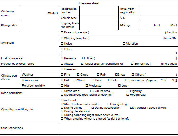
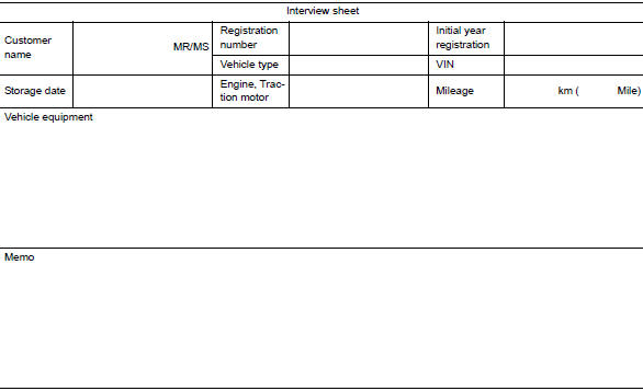
Diagnostic Work Sheet
Description
- In general, customers have their own criteria for a symptom. Therefore, it is important to understand the symptom and status well enough by interviewing the customer about the symptom carefully. To systemize all the information for the diagnosis, prepare the interview sheet referring to the interview points.
- In some cases, multiple conditions that appear simultaneously may cause a DTC to be detected.
INTERVIEW SHEET SAMPLE
ADDITIONAL SERVICE WHEN REPLACING CHASSIS CONTROL MODULE
Description
When replaced the chassis control module, configuration of the chassis control module is required. Refer to DAS-205, "Work Procedure".
CONFIGURATION (CHASSIS CONTROL MODULE)
Work Procedure
CAUTION:
- Use ‚ÄúManual Configuration‚ÄĚ only when ‚ÄúTYPE ID‚ÄĚ of the chassis control module cannot be read.
- After configuration, turn the ignition switch from OFF to ON and check that the chassis control warning to information display of combination meter displays OFF after staying illuminated for approximately two seconds.
- If an error occurs during configuration, start over from the beginning.
1.CHECKING TYPE ID (1)
Use FAST (service parts catalogue) to search the chassis control module of the applicable vehicle and find ‚ÄúType ID‚ÄĚ.
Is ‚ÄúType ID‚ÄĚ displayed? YES >> Print out ‚ÄúType ID‚ÄĚ and GO TO 2.
NO >> ‚ÄúConfiguration‚ÄĚ is not required for the chassis control module. Replace in the usual manner. Refer to DAS-277, "Removal and Installation".
2.CHECKING TYPE ID (2)
 CONSULT Configuration
- Select ‚ÄúBefore Replace ECU‚ÄĚ of ‚ÄúRead/Write Configuration‚ÄĚ.
- Check that ‚ÄúType ID‚ÄĚ is displayed on the CONSULT screen.
Is ‚ÄúType ID‚ÄĚ displayed? YES >> GO TO 3.
NO >> GO TO 7.
3.VERIFYING TYPE ID (1)
 CONSULT Configuration
Compare a ‚ÄúType ID‚ÄĚ displayed on the CONSULT screen with the one searched by using FAST (service parts catalogue) to check that these ‚ÄúType ID‚ÄĚ agree with each other.
NOTE: For the ‚ÄúType ID‚ÄĚ searched by using FAST (service parts catalog), use the last five digits of the ‚ÄúType ID‚ÄĚ.
>> GO TO 4.
4.SAVING TYPE ID
 CONSULT Configuration
Save ‚ÄúType ID‚ÄĚ on CONSULT.
>> GO TO 5.
5.REPLACING CHASSIS CONTROL MODULE (1)
Replace the chassis control module. Refer to DAS-277, "Removal and Installation".
>> GO TO 6.
6.WRITING (AUTOMATIC WRITING)
 CONSULT Configuration
- Select ‚ÄúAfter Replace ECU‚ÄĚ of ‚ÄúRe/programming, Configuration‚ÄĚ or that of ‚ÄúRead / Write Configuration‚ÄĚ.
- Select the ‚ÄúType ID‚ÄĚ agreeing with the one stored on CONSULT and the one searched by using FAST (service parts catalogue) to write the ‚ÄúType ID‚ÄĚ into the chassis control module.
NOTE: For the ‚ÄúType ID‚ÄĚ searched by using FAST (service parts catalog), use the last five digits of the ‚ÄúType ID‚ÄĚ.
>> GO TO 9.
7.REPLACING CHASSIS CONTROL MODULE (2)
Replace the chassis control module. Refer to DAS-277, "Removal and Installation".
>> GO TO 8.
8.WRITING (MANUAL WRITING)
CONSULT Configuration
- Select ‚ÄúManual Configuration‚ÄĚ.
- Select the ‚ÄúType ID‚ÄĚ searched by using FAST (service parts catalogue) to write the ‚ÄúType ID‚ÄĚ into the chassis control module.
NOTE: For the ‚ÄúType ID‚ÄĚ searched by using FAST (service parts catalog), use the last five digits of the ‚ÄúType ID‚ÄĚ. >> GO TO 9.
9.VERIFYING TYPE ID (2)
Compare ‚ÄúType ID‚ÄĚ written into the chassis control module with the one searched by using FAST (service parts catalogue) to check that these ‚ÄúType ID‚ÄĚ agree with each other.
NOTE: For the ‚ÄúType ID‚ÄĚ searched by using FAST (service parts catalog), use the last five digits of the ‚ÄúType ID‚ÄĚ. >> GO TO 10.
10.CHECKING CHASSIS CONTROL WARNING
- Turn the ignition switch OFF.
- Turn the ignition switch ON and check that the chassis control warning to information display of combination meter displays OFF after staying illuminated for approximately two seconds.
CAUTION: Never start the engine. Is the inspection result normal? YES >> GO TO 11.
NO >> Perform the ‚ÄúSelf Diagnostic Result‚ÄĚ of ‚ÄúCHASSIS CONTROL‚ÄĚ. Refer to DAS-182, "CONSULT Function".
11.PERFORMING SUPPLEMENTARY WORK
- Perform the self-diagnosis of all systems.
- Erase self-diagnosis results.
>> End of work.
 Wiring diagram
CHASSIS CONTROL
Wiring Diagram
...
 DTC/circuit diagnosis
C1B92-00 BRAKE CONTROL SYSTEM
DTC Description
DTC DETECTION LOGIC
DTC
Display Item
(Trouble diagnosis content)
Malfunction detected condition
C1B92-00
BRAKE ...
Other materials:
P0605 ECM
DTC Description
DTC DETECTION LOGIC
DTC No.
CONSULT screen terms
(Trouble diagnosis content)
DTC detecting condition
P0605
ECM
[Internal control module read only memory
(ROM) error]
Malfunction in the internal ROM of ECM.
POSSIBLE CAUSE
ECM
FAIL-SAFE
T ...
Console box
Console box
Upper half
Pull up on the driver’s side latch to open the
upper half of the console box.
The upper half of the console box may be used for
storage of cellular phones. An access hole is
provided at the front of the upper half of the
console box for a phone or iPod¬ģ cord rout ...
Front washer nozzle and tube
Exploded View
Cowl top cover
Front washer tube
Front washer nozzle (LH)
Front washer nozzle (RH)
Pawl
Clip
Exploded View
Cowl top cover
Front washer tube
Clip
Removal and Installation - Front Washer Nozzle
REMOVAL
Remove front wiper arms (LH ...
