Nissan Rogue Service Manual: Basic inspection
DIAGNOSIS AND REPAIR WORKFLOW
Trouble Diagnosis Flow Chart

Trouble Diagnosis Procedure
INTERVIEW WITH CUSTOMER
Interview with the customer is important to detect the root cause of CAN communication system errors and to understand vehicle condition and symptoms for proper trouble diagnosis.
Points in interview
- What: Parts name, system name
- When: Date, Frequency
- Where: Road condition, Place
- In what condition: Driving condition/environment
- Result: Symptom
NOTE:
- Check normal units as well as error symptoms.
- Example: Circuit between ECM and the combination meter is judged normal if the customer indicates tachometer functions normally.
- When a CAN communication system error is present, multiple control units may malfunction or go into failsafe mode.
- Indication of the combination meter is important to detect the root cause because it is the most obvious to the customer, and it performs CAN communication with many units.
INSPECTION OF VEHICLE CONDITION
Check whether the symptom is reproduced or not.
NOTE: Do not turn the ignition switch OFF or disconnect the battery cable while reproducing the error. The error may temporarily correct itself, making it difficult to determine the root cause.
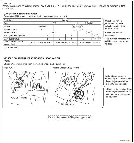
CHECK OF CAN SYSTEM TYPE (HOW TO USE CAN SYSTEM TYPE SPECIFICATION CHART)
Determine CAN system type based on vehicle equipment.
NOTE:
- This chart is used if CONSULT does not automatically recognize CAN system type
- • There are two styles for CAN system type specification charts. Depending on the number of available system types, either style A or style B may be used.
CAN System Type Specification Chart (Style A)
NOTE: CAN system type is easily checked with the vehicle equipment identification information shown in the chart.
CAN System Type Specification Chart (Style B)
NOTE: CAN system type is easily checked with the vehicle equipment identification information shown in the chart.
CREATE INTERVIEW SHEET
Fill out the symptom described by the customer, vehicle condition, and CAN system type on the interview sheet.
Interview Sheet (Example)
DETECT THE ROOT CAUSE
CAN diagnosis function of CONSULT detects the root cause.
 System description
CAN COMMUNICATION SYSTEM
System Description
CAN communication is a multiplex communication system. This enables the
system to transmit and receive
large quantities of data at high speed by c ...
 CAN
CAN
...
Other materials:
Operating range
Operating range
The Intelligent Key functions can only be used
when the Intelligent Key is within the specified
operating range.
When the Intelligent Key battery is almost discharged
or strong radio waves are present near
the operating location, the Intelligent Key system’s
operating ...
Glove box assembly and housing
Removal and Installation
REMOVAL
Release instrument side finisher (RH) (1) pawls using a suitable
tool and remove.
: Pawl
NOTE:
LH side shown; RH similar.
Release the glove box damper (1) from the glove box assembly
(2) as shown.
Release the glove box assembly pawls ...
Oil seal
VALVE OIL SEAL
VALVE OIL SEAL : Removal and Installation
REMOVAL
Remove camshafts. Refer to EM-64, "Removal and Installation".
Remove valve lifters. Refer to EM-56, "Disassembly and Assembly".
Rotate crankshaft, and set piston whose valve oil seal is t ...
