Nissan Rogue (T33) 2021-Present Service Manual: B272c-34 Corner Sensor [fr]
DTC Description
DTC DETECTION LOGIC
| DTC | CONSULT screen items (Trouble diagnosis content) | DTC detection condition | ||
|---|---|---|---|---|
| B272C-34 |
CORNER SENSOR [FR] (Corner sensor [FR]) |
Diagnosis condition | When ignition switch is ON | |
| Signal (terminal) | Front sonar sensor signal RH outer | |||
| Threshold | An abnormal sensor signal is input from sonar sensor (Pulse signal high side is short) | |||
| Diagnosis delay time | 4 seconds or more | |||
POSSIBLE CAUSE
-
Harness and connector between sonar control unit and front sonar sensor RH outer
-
Front sonar sensor RH outer
FAIL-SAFE
Stop the obstacle detection function
CONFIRMATION PROCEDURE
PERFORM DTC CONFIRMATION PROCEDURE
 With CONSULT
-
Turn ignition switch ON.
-
Turn ignition switch OFF and wait at least 30 seconds.
-
Turn ignition switch ON and wait at least 30 seconds or more.
-
Select ŌĆ£Self Diagnostic ResultŌĆØ mode of ŌĆ£SONARŌĆØ using CONSULT.
-
Check the DTC.
Is DTC ŌĆ£B272CŌĆō34ŌĆØ detected?
YES>>Refer to Diagnosis Procedure.
NO-1>>To check malfunction symptom before repair: Refer to Intermittent Incident.
NO-2>>Confirmation after repair: INSPECTION END
Diagnosis Procedure
CHECK FRONT SONAR SENSOR SIGNAL RH OUTER CIRCUIT (OPEN)
-
Turn ignition switch OFF.
-
Disconnect sonar control unit connector and front sonar sensor RH outer connector.
-
Check continuity between sonar control unit harness connector and front sonar sensor RH outer connector
Sonar control unit Front sonar sensor RH outer Continuity Connector Terminal Connector Terminal B20 4 E307 2 Existed
Is the inspection result normal?
YES>>GO TO 2.
NO>>Repair the harness or connector.
CHECK FRONT SONAR SENSOR RH OUTER GROUND CIRCUIT
Check continuity between sonar control unit harness connector and front sonar sensor RH outer harness connector.
| Sonar control unit | Front sonar sensor RH outer | Continuity | ||
|---|---|---|---|---|
| Connector | Terminal | Connector | Terminal | |
| B20 | 13 | E307 | 3 | Existed |
Is the inspection result normal?
YES>>GO TO 3.
NO>>Repair the harness or connector.
CHECK FRONT SONAR SENSOR SIGNAL RH OUTER
-
Connect sonar control unit connector and front sonar sensor RH outer connector.
-
Turn ignition switch ON.
-
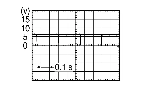
Check the signal between sonar control unit terminals as per the following condition.
+ ŌłÆ Condition Voltage Sonar control unit Connector Terminal Connector Terminal B20 4 B20 13 -
Shift position is in R position.
-
When the sensor is detecting an obstacle
-
Is the inspection result normal?
YES>>Replace the sonar control unit. Refer to Removal and Installation.
NO>>Replace the front sonar sensor RH outer. Refer to Removal and Installation.
Other materials:
Chassis Can Communication 4 Circuit
Diagnosis Procedure
CHECK NETWORK DIAGNOSIS
Check the "Network diagnosis" results from CONSULT to see that the diagnostic CAN communication circuit have no malfunction.
Are the diagnostic CAN communication circuit normal?
YES>>
GO TO 2.
NO>>
Check and repair diagnostic CAN commu ...
P2135 Tp Sensor
DTC Description
DTC DETECTION LOGICNOTE:
If DTC P2135 is displayed with DTC P06B0, first perform the trouble diagnosis for DTC P06B0. Refer to DTC Description.
DTC
CONSULT screen terms
(Trouble diagnosis content)
DTC detection condition
P2135
00
TP SENSOR-B1
(Throttle/Pedal ...
B2e01-96 Tcu
DTC Description
DTC DETECTION LOGIC DTC No.
CONSULT screen terms
(Trouble diagnosis content) DTC detection condition
B2E01-96
Internal battery
(Internal battery)
Diagnosis condition
When ignition switch is ON
Signal (terminal)
Internal battery
Threshold
Internal ba ...