Nissan Rogue (T33) 2021-Present Service Manual: Automatic Brake Hold :: System Description
Component Parts
Chassis Control System - With Propilot Assist 2.1
Component Parts Location
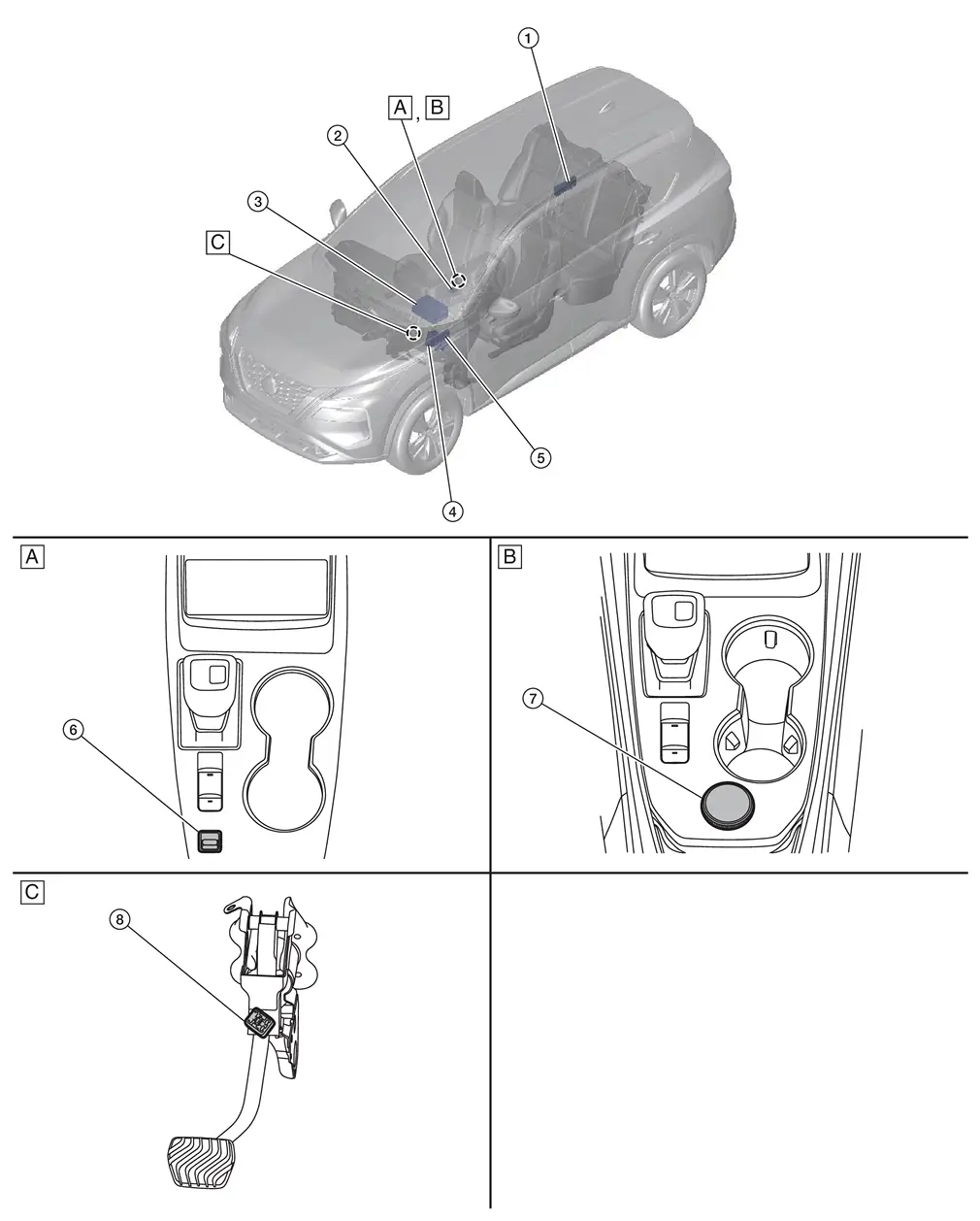
| A. | Center console finisher (2WD) | B. | Center console finisher (AWD) | C. | Brake pedal assembly removed |
| No. | Component | Function |
|---|---|---|
| 1. | Power Network Seperate Relay | Refer to Component Parts Location for detailed component location. |
| 2. | Parking Brake Switch | Refer to Parking Brake Switch. |
| 3. | 12V Sub Battery (Lithium Ion Battery) | Refer to Component Parts Location for detailed component location. |
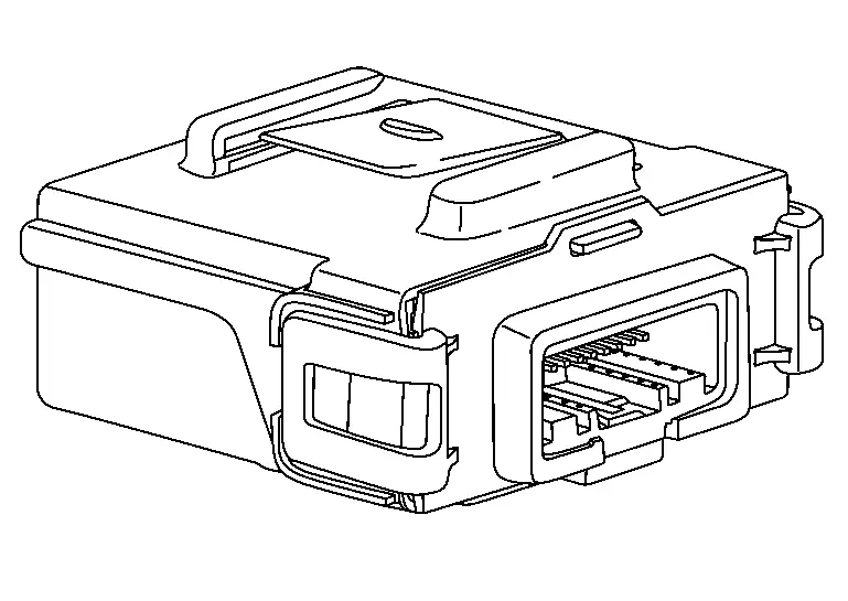
| 4. | Chassis Control Module | Refer to Chassis Control Module. |
| 5. | BCM (Body Control Module) | Refer to Component Parts Location for detailed component location. |
| 6. | Drive Mode Select Switch (2WD) | Refer to Component Parts Location. |
| 7. | vDrive Mode Select Switch (AWD) | Refer to Component Parts Location. |
| 8. | Stop Lamp Switch | Refer to Component Parts Location. |
Chassis Control System - Without Propilot Assist 2.1
Component Parts Location
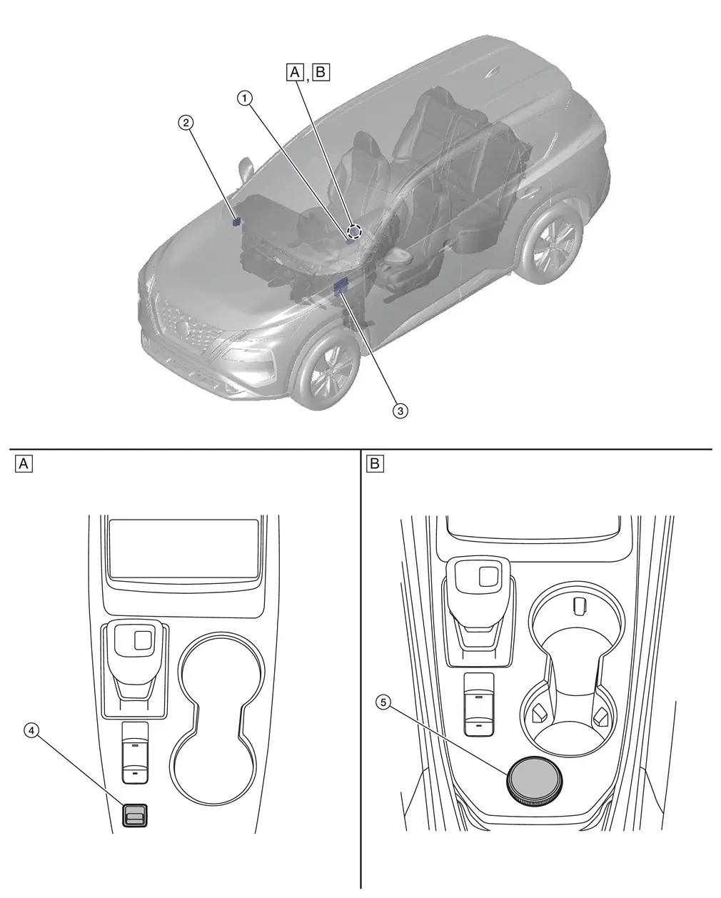
| A. | Center console finisher (2WD) | B. | Center console finisher (AWD) | ||
| No. | Component | Function |
|---|---|---|
| 1. | Parking Brake Switch | Refer to Parking Brake Switch. |
| 2. | Chassis Control Module | Refer to Chassis Control Module. |
| 3. | BCM (Body Control Module) |
Refer to Component Parts Location for detailed component location. . |
| 4. | Drive Mode Select Switch (2WD) | Refer to Component Parts Location. |
| 5. | Drive Mode Select Switch (AWD) | Refer to Component Parts Location. |
Chassis Control Module
FUNCTIONS WITHIN THE SYSTEM
Chassis control module part controls automatic brake hold function according to the signals from each sensor, each switch and each control unit.
INDIVIDUAL FUNCTIONS WITHIN THE SYSTEM
-
Transmits automatic brake hold function activation request signal and automatic brake hold function deactivation request signal to ABS actuator and electric unit (control unit).
-
Transmits electric parking brake signal to ABS actuator and electric unit (control unit).
PARTS LOCATION
Refer to Component Parts Location.
Parking Brake Switch (Automatic Brake Hold Switch)
 NOTE:
NOTE:
-
Parking brake switch
 , automatic brake hold switch
  , and indicator
  are single unit.
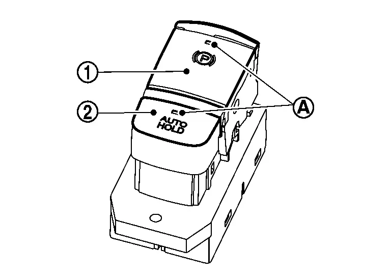
FUNCTIONS WITHIN THE SYSTEM
By operating automatic brake hold switch, turn ON/OFF automatic brake hold function.
NOTE:
Automatic brake hold function retains the last state until the driver changes the option even if the ignition switch OFF.
INDIVIDUAL FUNCTIONS WITHIN THE SYSTEM
-
Turns ON/OFF automatic brake hold switch, and turns ON/OFF automatic brake hold function by chassis control module.
-
According to the control of chassis control module, automatic brake hold switch indicator turns ON/OFF.
INDIVIDUAL OPERATION
-
A normal open type is used for automatic brake hold switch.
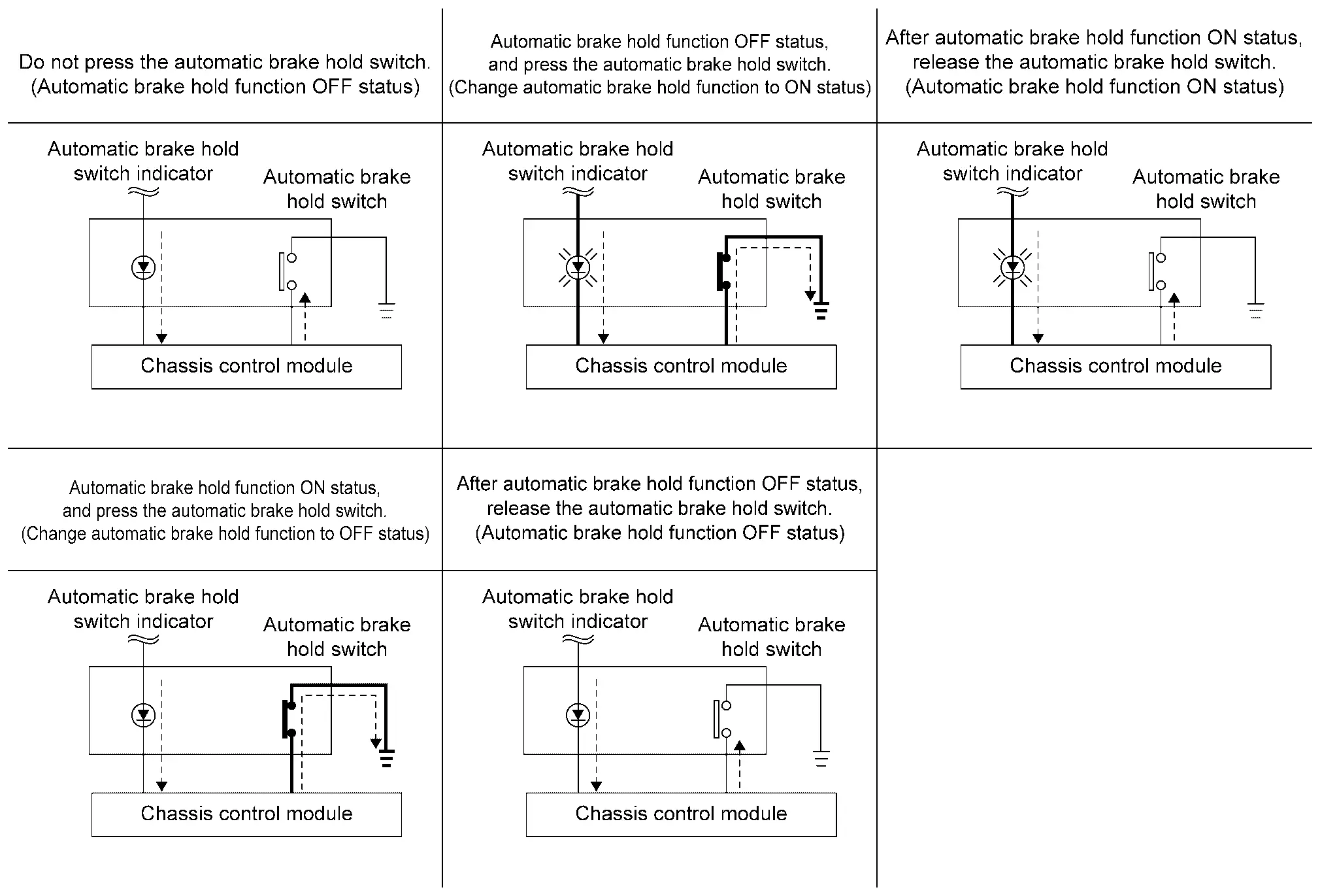
-
If automatic brake hold switch is pressed when automatic brake hold function is OFF, automatic brake hold function turns ON. In addition, automatic brake hold switch indicator illuminates.
NOTE:
Automatic brake hold function retains the last state until the driver changes the option even if the ignition switch OFF.
-
If automatic brake hold switch is pressed when automatic brake hold function is ON, automatic brake hold function turns OFF. In addition, automatic brake hold switch indicator turns OFF. [If automatic brake hold indicator lamp (white or green) is ON, it turns OFF.]
NOTE:
To turn OFF automatic brake hold function while the brakes are held by automatic brake hold function, press automatic brake hold switch while depressing brake pedal.
PARTS LOCATION
Refer to Component Parts Location.
System
System Description
-
Automatic brake hold function is used for holding the brakes automatically when the vehicle is stopped by a brake operation.
-
Automatic brake hold function is used to reduce continuous brake pedal operations by the driver.
-
Automatic brake hold function is controlled by chassis control module.
-
Chassis control module receives information required for controlling via CAN communication and from each switch to control automatic brake hold function.
SYSTEM DIAGRAM (WITHOUT TELEMATICS SYSTEM)
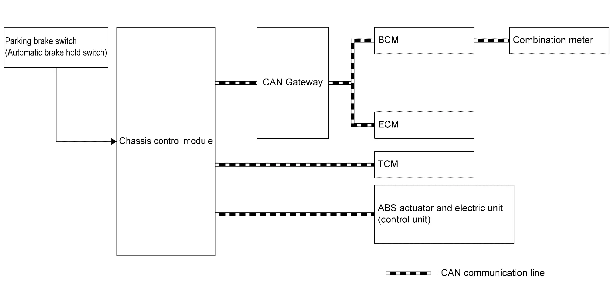
| Component | Signal description |
|---|---|
| ECM |
Mainly transmits the following signals to chassis control module via CAN communication.
|
| TCM |
Mainly transmits the following signals to chassis control module via CAN communication.
|
| ABS actuator and electric unit (control unit) |
Mainly transmits the following signals to chassis control module via CAN communication.
|
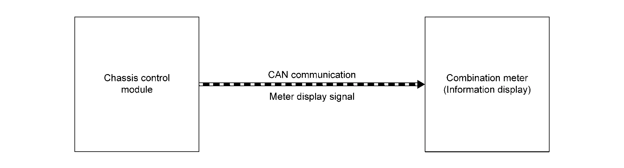
| Combination meter |
Mainly receives the following signals from chassis control module via CAN communication.
|
| BCM |
Mainly transmits the following signals to chassis control module via CAN communication.
|
| Chassis control module | Chassis Control Module |
|
Parking brake switch (automatic brake hold switch) |
Parking Brake Switch (Automatic Brake Hold Switch) |
SYSTEM DIAGRAM (WITH TELEMATICS SYSTEM)
| Component | Signal description |
|---|---|
| ECM |
Mainly transmits the following signals to ABS actuator and electric unit (control unit) via CAN communication.
|
| TCM |
Mainly transmits the following signals to ABS actuator and electric unit (control unit) via CAN communication.
|
| ABS actuator and electric unit (control unit) |
Mainly transmits the following signals to chassis control module via CAN communication.
Mainly transmits the following signals to BCM via CAN communication.
Mainly transmits the following signals to ECM via CAN communication.
Mainly transmits the following signals to combination meter via CAN communication.
|
| Combination meter |
Mainly transmits the following signals from chassis control module via CAN communication.
|
| BCM |
Mainly transmits the following signals to ABS actuator and electric unit (control unit) via CAN communication.
|
| Chassis control module | Refer to Chassis Control Module. |
| Parking brake switch (automatic brake hold switch) | Refer to Parking Brake Switch (Automatic Brake Hold Switch). |
OPERATION
Automatic Brake Hold Function ON (Operation Permitted)
If automatic brake hold switch is pressed when automatic brake hold function is OFF, automatic brake hold function turns ON. In addition, automatic brake hold switch indicator illuminates.
NOTE:
Automatic brake hold function retains the last state until the driver changes the option even if the ignition switch OFF.
Automatic Brake Hold Function OFF (Operation Not Permitted)
If automatic brake hold switch is pressed when automatic brake hold function is ON, automatic brake hold function turns OFF. In addition, automatic brake hold switch indicator turns OFF. [If automatic brake hold indicator lamp (white or green) is ON, it turns OFF.]
NOTE:
To turn OFF automatic brake hold function while the brakes are held by automatic brake hold function, press automatic brake hold switch while depressing brake pedal.
Standby
When all of the following conditions are satisfied, automatic brake hold function enters in the standby state, and automatic brake hold indicator lamp (white) illuminates.
-
Seat belt (driver side) is fastened
-
Electric parking brake is released
-
Shift position is not in the P
-
Automatic brake hold switch is ON
Operation
If all of the following conditions are satisfied in the standby state, automatic brake hold function operates, and the color of automatic brake hold indicator lamp changes from white to green. In addition, automatic brake hold display appears.
NOTE:
Although the conditions are satisfied in the standby state, automatic brake hold function may not operate depending on how far brake pedal is depressed. When automatic brake hold function does not operate, depress brake pedal far enough until automatic brake hold indicator lamp (green) turns ON.
-
Vehicle speed: 0 km/h (0 MPH)
-
Brake pedal is depressed
-
Automatic brake hold function is in the standby state [automatic brake hold switch indicator and automatic brake hold indicator lamp (white) are illuminated]
-
Not on a steep slope
-
Seat belt (driver side) is fastened
-
Electric Parking Brake is released
-
Shift position is not in the P
Release (Starting Vehicle)
If the following condition is satisfied while automatic brake hold function is being applied, automatic brake hold function is released. (The color of automatic brake hold indicator lamp changes from green to white.)
-
The vehicle is started
NOTE:
-
Shift position is not in the P and N.
-
Automatic brake hold function is operated by applying sufficient braking force to hold the Nissan Ariya vehicle in its place, so there are cases when this hold function is maintained even if the accelerator pedal is depressed. In this situation, it is advised to depress the brake pedal first, then to turn OFF automatic brake hold switch. This will cancel the hold function.
Release (Automatic Brake Hold Switch)
If the following condition is satisfied while automatic brake hold function is being applied, automatic brake hold function is released. (Automatic brake hold indicator lamp turns OFF.)
-
Operate automatic brake hold switch while depressing brake pedal.
Release (Changing to Electric Parking Brake)
If any of the following conditions are met while automatic brake hold function is being applied, electric Parking Brake is operated automatically, and automatic brake hold function is released. (Automatic brake hold indicator lamp turns OFF.)
-
Operation of Automatic brake hold function is continued for approximately 3 minutes
-
Shift position is in the P
-
The electric parking brake system is applied manually
-
Seat belt (driver side) is unfastened
-
Door (driver side) is opened
-
Ignition switch OFF
-
A malfunction is detected in Automatic brake hold function
Parking
-
If shift position is in the P while Automatic brake hold function is being applied, Automatic brake hold function is released. (Automatic brake hold indicator lamp turns OFF.)
-
If the electric Parking Brake is applied while Automatic brake hold function is being applied, Automatic brake hold function is released. (Automatic brake hold indicator lamp turns OFF.)
Timing Chart
-
The vehicle is started while automatic brake hold function is being applied
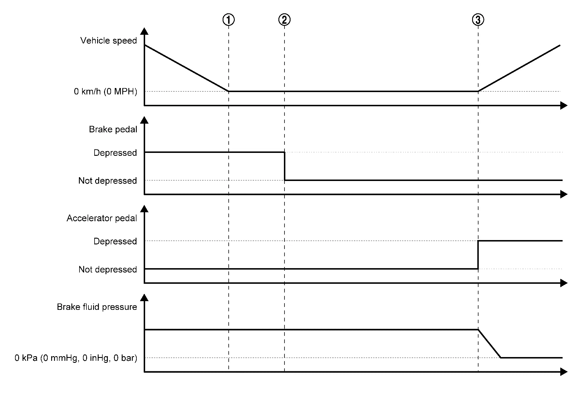
When the Nissan Ariya vehicle is stopped by a brake operation by the driver, maintaining of brake fluid pressure is started. Automatic brake hold function is applied (this function holds brake fluid pressure even after the driver has released brake pedal). 
When the driver performs starting operation, automatic brake hold function is released (brake fluid pressure is decreased). -
Changing the Nissan Ariya vehicle holding method to electric parking brake while automatic brake hold function is being applied
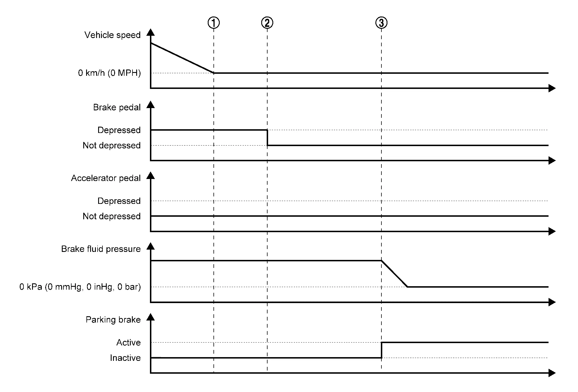
When the Nissan Ariya vehicle is stopped by a brake operation by the driver, maintaining of the brake fluid pressure is started. Automatic brake hold function is applied (this function holds brake fluid pressure even after the driver has released brake pedal). If the conditions for changing to electric parking brake are satisfied while automatic brake hold function is being applied, the method of holding the Nissan Ariya vehicle stopped is automatically changed to electric parking brake.
Fail-safe
Refer to Fail-safe.
Warning/indicator/chime List
Warning Lamp/Indicator Lamp
| Name | Design | Layout/Function |
|---|---|---|
| Automatic brake hold indicator lamp |  |
For layout
|
|
For function
|
Information Display (combination Meter)
Chassis Control Warning
Refer to Chassis Control Warning.
Automatic Brake Hold Warning
DESIGN/PURPOSE
Notifies the driver when the vehicle is moved or may start moving while automatic brake hold function is being applied.
Waning Message
| Design | Warning message | Description |
|---|---|---|
| — | Press brake pedal to prevent rolling | When the Nissan Ariya vehicle moves or possibly moves while automatic brake hold function activates. |
| Caution Steep slope | When the automatic brake hold function activates on the steep slope. | |
| Steep Slope Apply foot brake | When the brake pedal is not depressed while the automatic brake hold function activates on the steep slope for 3 minutes approximately. | |
| Press brake to operate switch |
|
SYNCHRONIZATION WITH WARNING CHIME
| Warning message | — |
|---|---|
| Press brake pedal to prevent rolling | Applicable |
| Caution Steep slope | No |
| Steep Slope Apply foot brake | No |
| Press brake to operate switch | No |
SYNCHRONIZATION WITH MASTER WARNING LAMP
| Warning message | — |
|---|---|
| Press brake pedal to prevent rolling | Applicable |
| Caution Steep slope | No |
| Steep Slope Apply foot brake | No |
| Press brake to operate switch | No |
SYSTEM DIAGRAM
WARNING MESSAGE DISPLAY CONDITION
When all of the following conditions are satisfied.
-
Automatic brake hold function applied
-
Vehicle is moved; vehicle may start moving; or a malfunction is detected in automatic brake hold function (chassis control module). Refer to Fail-safe.
Diagnosis System (chassis Control Module)
CONSULT Function
-
Chassis control module: Refer to CONSULT Function. (Without telematics system)
-
Chassis control module: Refer to CONSULT Function. (With telematics system)
Other materials:
Symptom Diagnosis. Manual Function Does Not Operate
All Component
Diagnosis Procedure
CHECK DRIVER SEAT CONTROL UNIT POWER SUPPLY AND GROUND CIRCUIT
Check driver seat control unit power supply and ground circuit. Refer to Diagnosis Procedure.
Is the inspection result normal?
YES>>
GO TO 2.
NO>>
Repair or replace the malfunctioni ...
Diagnosis System (hvac)
CONSULT Function
CONSULT performs the following functions via CAN communication with A/C amp. Diagnosis mode Function
Self diagnosis result
Display non-network DTC which A/C amp. memorizes
ECU identification
The A/C amp. part number is displayed
Active Test
The signals used t ...
Removal and Installation. Electrically-Driven Intelligent Brake Unit
Exploded View
Reservoir cap
Oil strainer
Electrically-driven intelligent brake unit
Clevis
Gasket
: N·m (kg-m, ft-lb)
: Always replace after every disassembly.
Removal & Installation
REMOVALCAUTION:
While electrically-driven ...