Nissan Rogue Service Manual: Water outlet and water piping
Exploded View
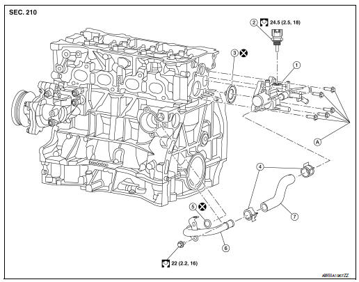
- Water outlet
- Water temperature sensor
- Water outlet O-ring
- Clamp
- Heater pipe O-ring
- Heater pipe
- Water hose
- Refer to INSTALLATION
Removal and Installation
WARNING: Do not remove the radiator cap when the engine is hot. Serious burns could occur from high-pressure engine coolant escaping from the radiator. Wrap a thick cloth around the cap. Slowly push down and turn it a quarter turn to allow built-up pressure to escape. Carefully remove the cap by pushing it down and turning it all the way.
NOTE: When removing components such as hoses, tubes/lines, etc., cap or plug openings to prevent fluid from spilling.
CAUTION: Perform when the engine cold.
REMOVAL
- Drain engine coolant from the radiator. Refer to CO-8, "Draining".
- Remove the upper radiator hose from water outlet.
- Remove resonator assembly. Refer to EM-24, "Exploded View".
- Remove battery tray. Refer to PG-75, "Exploded View".
- Remove ECM/TCM bracket, (if necessary).
- Disconnect harness connector from water temperature sensor.
- Remove water temperature sensor from water outlet, (if necessary).
- Remove heater hoses from water outlet.
NOTE: Note location of heater hoses prior to removal to serve as an installation aid.
- Remove water hoses from water outlet.
NOTE: Note location of heater hoses prior to removal to serve as an installation aid.
- Remove water hoses from electric throttle control actuator.
- Remove the water outlet.
INSTALLATION
- Tighten water outlet bolts in sequence to specification.
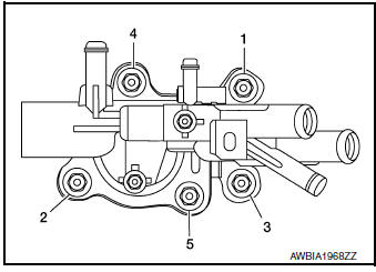
22 N·m (2.2 kg-m, 16 ft-lb)
Installation of remaining components is in the reverse order of removal.
CAUTION:
- Do not reuse heater pipe O-ring.
- Do not reuse water outlet O-ring.
- To install heater pipe, first apply a mild soap to the O-ring and quickly insert the heater pipe into the housing.
- Do not spill coolant in engine compartment. Use a shop cloth to absorb coolant.
After installation, refill coolant and check for leaks. Refer to CO-9, "Refilling" and CO-8, "Inspection".
 Thermostat and water control
valve
Thermostat and water control
valve
Exploded View
Water inlet
Thermostat
Rubber ring
To radiator hose (lower)
NOTE:
When removing components such as hoses, tubes/lines, etc., cap or plug opening ...
 Service data and specifications (SDS)
Periodical Maintenance Specification
ENGINE COOLANT CAPACITY (APPROXIMATE)
Radiator
Thermostat
...
Other materials:
Interior room lamp control system
Wiring Diagram
...
Periodic maintenance
REAR DIFFERENTIAL GEAR OIL
Inspection
OIL LEAKS
Make sure that oil is not leaking from final drive assembly or around it.
OIL LEVEL
Remove filler plug (1) and check oil level from filler plug
mounting
hole as shown.
CAUTION:
Do not start engine while checking oil level.
&nbs ...
Removal and installation
REAR WHEEL HUB
Exploded View
Suspension arm
Back plate
Wheel stud
Wheel hub and bearing
Disc brake rotor
Plug
Removal and Installation
REMOVAL
Wheel Hub and Bearing
Remove the wheel and tire using power tool. Refer to WT-57,
"Adjustment".
Remove t ...
