Nissan Rogue Service Manual: Unit removal and installation
ENGINE ASSEMBLY
Exploded view
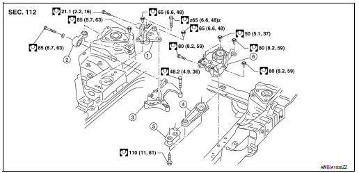
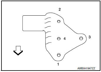
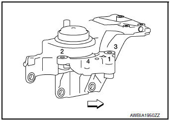
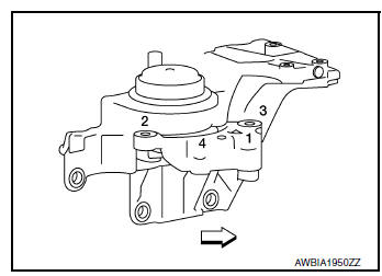
- Engine mounting insulator (RH)
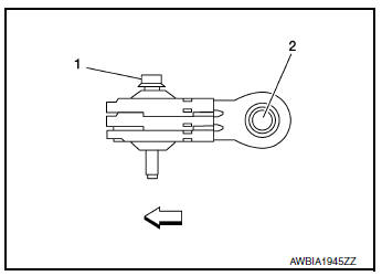
- Upper torque rod (RH)
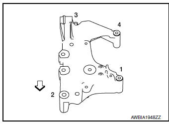
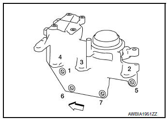
- Engine mounting bracket (RH)
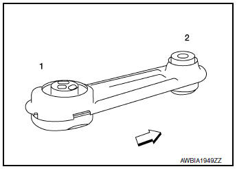
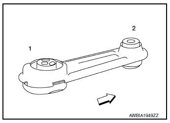
- Lower torque rod
- Torque rod bracket
- Engine mounting insulator (LH)
Removal and installation (FWD)
WARNING:
- Situate the vehicle on a flat and solid surface.
- Place chocks at front and back of rear wheels.
- Attach proper slingers and bolts described in PARTS CATALOG if engine slingers are not equipped.
CAUTION:
- Always be careful to work safely, avoid forceful or uninstructed operations.
- Do not start working until exhaust system and engine coolant is cool enough.
- If items or work required are not covered by the engine section, refer to the applicable sections.
- Always use the support point specified for lifting.
- Use either 2-pole lift type or separate type lift as best you can. If board-on type is used for unavoidable reasons, support at the rear axle jacking point with a transmission jack or similar tool before starting work, in preparation for the backward shift of center of gravity.
- For supporting points for lifting and jacking point at rear axle, refer to GI-29, "Garage Jack and Safety Stand and 2-Pole Lift".
NOTE: When removing components such as hoses, tubes/lines, etc., cap or plug openings to prevent fluid from spilling.
REMOVAL
- Remove hood assembly. Refer to DLK-233, "HOOD ASSEMBLY : Removal and Installation".
- Relieve fuel system pressure. Refer to EC-144, "Work Procedure".
- Remove fender protector. Refer to EXT-28, "FENDER PROTECTOR : Removal and Installation".
- Remove battery tray. Refer to PG-76, "Removal and Installation (Battery Tray)".
- Remove air cleaner and air duct. Refer to EM-24, "Removal and Installation".
- Remove harness grounds.
- Remove harness bracket retainer.
- Remove relay box assembly from underhood.
- Drain engine coolant. Refer to CO-8, "Draining".
- Remove radiator hose (upper/lower). Refer to CO-13, "Exploded View".
- Disconnect heater hose inlet from engine side.
- Disconnect heater hose outlet from engine side.
- Disconnect control cable. Refer to TM-197, "Removal and Installation".
- Remove EVAP and vacuum hose from intake manifold.
- Remove quick connector cap from fuel hose and fuel tube.
- Disconnect fuel hose.
- Remove harness ground wire bolt from generator bracket.
- Remove fuse box cover.
- Disconnect harness connector from fuse box.
- Disconnect harness connector from IPDM E/R.
- Disconnect harness connector from cooling fan controller.
- Disconnect harness connector from refrigerant pressure sensor.
- Remove low-pressure pipe. Refer to HA-32, "LOW-PRESSURE PIPE : Removal and Installation".
- Remove high-pressure pipe. Refer to HA-34, "HIGH-PRESSURE PIPE : Removal and Installation".
- Remove steering knuckles (LH/RH). Refer to FSU-9, "Exploded View".
- Remove front drive shaft (LH/RH). Refer to FAX-18, "Removal and Installation (LH)" and FAX-20, "Removal and Installation (RH)".
- Remove front exhaust tube. Refer to EX-5, "Exploded View".
- Remove front suspension member. Refer to FSU-20, "Removal and Installation".
- Remove CVT fluid cooler hoses from radiator. Refer to CO-13, "Exploded View".
- Disconnect battery negative cable ground bolt from transaxle.
- Remove upper torque rod (RH).
- Remove engine mounting bracket (RH).
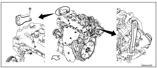
- Install engine slingers into front left of engine mount bracket (RH) and rear right of cylinder head.
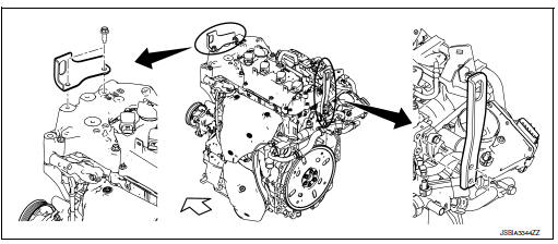
 : Engine front
Slinger bolts
Cylinder head side : 22.0 N·m (2.2 kg-m, 16 ft-lb)
Engine mount bracket side : 48.1 N·m (4.9 kg-m, 35 ft-lb)
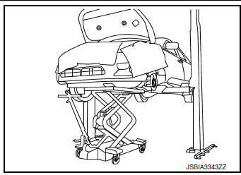
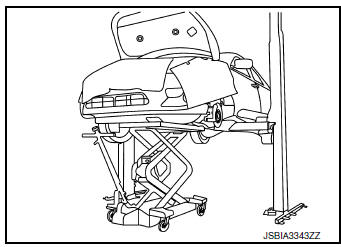
- Support weight of engine and transaxle assembly with a shop crane.
- Use a suitable jack and securely support bottom of the engine
and the transaxle assembly.
CAUTION: Put a piece of wood or an equivalent as the supporting surface, secure a completely stable condition.
- Slowly lower engine and transaxle assembly.
CAUTION:
- As engine and transaxle assembly is being lowered ensure there is no interference with body or engine harness connectors.
- Before and during this procedure, always check if any harnesses are left connected.
- Avoid any damage to, or any oil/grease smearing or spills onto the engine mounting insulators.
- Disconnect harness connector from input speed sensor. Refer to TM-207, "Removal and Installation".
- Disconnect harness connector from output speed sensor. Refer to TM-209, "Removal and Installation".
- Disconnect harness connector from primary speed sensor. Refer to TM-208, "Removal and Installation".
- Remove PNP switch from transaxle assembly.
- Remove harness connector from transaxle assembly.
- Remove starter motor. Refer to STR-21, "Removal and Installation".
- Remove drive plate inspection cover from engine.
- Hold drive plate with suitable tool and remove torque converter nuts.
- Remove transaxle to engine mount bolts.
INSTALLATION
Installation is in the reverse order of removal.
NOTE:
- Tighten the transmission bolts to specification. Refer to TM-220, "Exploded View".
- Do not allow oil to get on mounting insulators. Be careful not to damage mounting insulators.
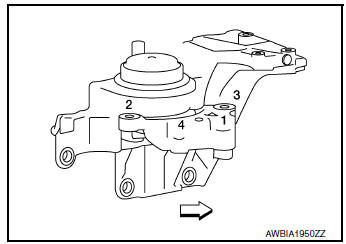
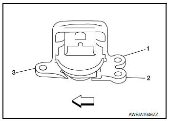
- Install the engine mount insulator (RH) as follows:
- Temporarily tighten the bolts.
- Tighten the bolts in sequence as shown to the specified torque.
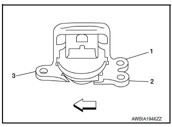
 : Front
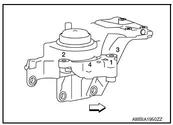
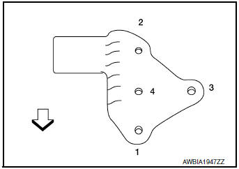
- Install the engine mounting bracket (RH).
- Temporarily tighten the bolts.
- Tighten the bolts in sequence as shown to the specified torque.
: Front
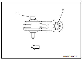
- Install the upper torque rod (RH) as follows:
- Temporarily tighten bolts.
- Tighten the bolts in sequence as shown to the specified torque.
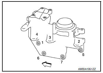
- Install the lower torque rod bolts as follows:
- Temporarily tighten the bolts.
- Tighten the bolts in sequence as shown to the specified torque.
: Front
- Install the lower torque rod bracket bolts as follows:
- Temporarily tighten the bolts.
- Tighten the bolts in sequence as shown to the specified torque.
: Front
Removal and installation (AWD)
WARNING:
- Situate the vehicle on a flat and solid surface.
- Place chocks at front and back of rear wheels.
- Attach proper slingers and bolts described in PARTS CATALOG if engine slingers are not equipped.
CAUTION:
- Always be careful to work safely, avoid forceful or uninstructed operations.
- Do not start working until exhaust system and engine coolant is cool enough.
- If items or work required are not covered by the engine section, refer to the applicable sections.
- Always use the support point specified for lifting.
- Use either 2-pole lift type or separate type lift as best you can. If board-on type is used for unavoidable reasons, support at the rear axle jacking point with a transmission jack or similar tool before starting work, in preparation for the backward shift of center of gravity.
- For supporting points for lifting and jacking point at rear axle, refer to GI-29, "Garage Jack and Safety Stand and 2-Pole Lift".
NOTE: When removing components such as hoses, tubes/lines, etc., cap or plug openings to prevent fluid from spilling.
REMOVAL
- Remove hood assembly. Refer to DLK-233, "HOOD ASSEMBLY : Removal and Installation".
- Relieve fuel system pressure. Refer to EC-144, "Work Procedure".
- Remove fender protector. Refer to EXT-28, "FENDER PROTECTOR : Removal and Installation".
- Remove battery tray. Refer to PG-76, "Removal and Installation (Battery Tray)".
- Remove air cleaner and air duct. Refer to EM-24, "Removal and Installation".
- Remove harness grounds.
- Remove harness bracket retainer.
- Remove relay box assembly from underhood.
- Drain engine coolant. Refer to CO-8, "Draining".
- Remove radiator hose (upper/lower). Refer to CO-13, "Exploded View".
- Disconnect heater hose inlet from engine side.
- Disconnect heater hose outlet from engine side.
- Disconnect control cable. Refer to TM-197, "Removal and Installation".
- Remove EVAP and vacuum hose from intake manifold.
- Remove quick connector cap from fuel hose and fuel tube.
- Disconnect fuel hose.
- Remove harness ground wire bolt from generator bracket.
- Remove fuse box cover.
- Disconnect harness connector from fuse box.
- Disconnect harness connector from IPDM E/R.
- Disconnect harness connector from cooling fan controller.
- Disconnect harness connector from refrigerant pressure sensor.
- Remove low-pressure pipe. Refer to HA-32, "LOW-PRESSURE PIPE : Removal and Installation".
- Remove high-pressure pipe. Refer to HA-34, "HIGH-PRESSURE PIPE : Removal and Installation".
- Remove steering knuckles (LH/RH). Refer to FSU-9, "Exploded View".
- Remove front drive shaft (LH/RH). Refer to FAX-18, "Removal and Installation (LH)" and FAX-52, "Removal and Installation (RH)".
- Remove front exhaust tube. Refer to EX-5, "Exploded View".
- Remove transfer assembly. Refer to DLN-70, "Removal and Installation".
- Remove front suspension member. Refer to FSU-20, "Removal and Installation".
- Remove CVT fluid cooler hoses from radiator. Refer to CO-13, "Exploded View".
- Disconnect battery negative cable ground bolt from transaxle.
- Remove upper torque rod (RH).
- Remove engine mounting bracket (RH).
- Install engine slingers into front left of engine mount bracket (RH) and rear right of cylinder head
 : Engine front
Slinger bolts
Cylinder head side : 22.0 N·m (2.2 kg-m, 16 ft-lb)
Engine mount bracket side : 48.1 N·m (4.9 kg-m, 35 ft-lb)
- Support weight of engine and transaxle assembly with a shop crane.
- Use a suitable jack and securely support bottom of the engine and the transaxle assembly.
CAUTION: Put a piece of wood or an equivalent as the supporting surface, secure a completely stable condition.
- Slowly lower engine and transaxle assembly.
CAUTION:
- As engine and transaxle assembly is being lowered ensure there is no interference with body or engine harness connectors.
- Before and during this procedure, always check if any harnesses are left connected.
- Avoid any damage to, or any oil/grease smearing or spills onto the engine mounting insulators.
- Disconnect harness connector from input speed sensor. Refer to TM-207, "Removal and Installation".
- Disconnect harness connector from output speed sensor. Refer to TM-209, "Removal and Installation".
- Disconnect harness connector from primary speed sensor. Refer to TM-208, "Removal and Installation".
- Remove PNP switch from transaxle assembly.
- Remove harness connector from transaxle assembly.
- Remove starter motor. Refer to STR-21, "Removal and Installation".
- Remove drive plate inspection cover from engine.
- Hold drive plate with suitable tool and remove torque converter nuts.
- Remove transaxle to engine mount bolts.
INSTALLATION
Installation is in the reverse order of removal.
NOTE:
- Tighten the transmission bolts to specification. Refer to TM-220, "Exploded View".
- Do not allow oil to get on mounting insulators. Be careful not to damage mounting insulators.
- Install the engine mount insulator (RH) as follows:
- Temporarily tighten the bolts.
- Tighten the bolts in sequence as shown to the specified torque.
 : Front
- Install the engine mounting bracket (RH).
- Temporarily tighten the bolts.
- Tighten the bolts in sequence as shown to the specified torque.

: Front
- Install the upper torque rod (RH) as follows:
- Temporarily tighten bolts.
- Tighten the bolts in sequence as shown to the specified torque.
- Install the lower torque rod bolts as follows:
- Temporarily tighten the bolts.
- Tighten the bolts in sequence as shown to the specified torque.
: Front
- Install the lower torque rod bracket bolts as follows:
- Temporarily tighten the bolts.
- Tighten the bolts in sequence as shown to the specified torque.
: Front
Inspection
INSPECTION AFTER INSTALLATION
- Before starting engine, check oil/fluid levels including engine coolant and engine oil. If less than required quantity, fill to the specified level. Refer to MA-11, "Fluids and Lubricants" (United States and Canada).
- Use procedure below to check for fuel leaks.
- Turn ignition switch ON (with engine stopped). With fuel pressure applied to fuel piping, check for fuel leaks at connection points.
- Start engine. With engine speed increased, check again for fuel leaks at connection points.
- Run engine to check for unusual noise and vibration.
NOTE: If hydraulic pressure inside timing chain tensioner drops after removal and installation, slack in the guide may generate a pounding noise during and just after engine start. However, this is normal. Noise will stop after hydraulic pressure rises.
- Warm up engine thoroughly to make sure there are no leaks of fuel, exhaust gas, or any oils/fluids including engine oil and engine coolant.
- Bleed air from passages in lines and hoses, such as in cooling system.
- After cooling down engine, again check oil/fluid levels including engine oil and engine coolant. Refill to specified level, if necessary.
- Summary of the inspection items:
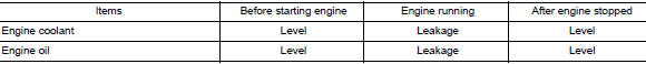
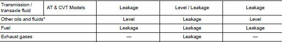
*: Power steering fluid, brake fluid, etc.
 Oil seal
VALVE OIL SEAL
VALVE OIL SEAL : Removal and Installation
REMOVAL
Remove camshafts. Refer to EM-64, "Removal and Installation".
Remove valve lifters. Refer to EM-56, " ...

Other materials:
Towing load/specification
TOWING LOAD/SPECIFICATION CHART
U.S. and Canada
Maximum Towing Capacity*1
1,100lb.
(500 kg)
Maximum Tongue Load
110 lb.
(50 kg)
Maximum Gross Combined Weight Rating
5,291 lb.
(2,400 kg)
*1: The towing capacity ...
Precaution
Precaution for Supplemental Restraint System (SRS) "AIR BAG" and "SEAT
BELT
PRE-TENSIONER"
The Supplemental Restraint System such as “AIR BAG” and “SEAT BELT PRE-TENSIONER”,
used along
with a front seat belt, helps to reduce the risk or severity of injury to the
...
Removal and installation
AUDIO UNIT
Exploded View
Audio unit bracket (LH)
Audio unit
Audio unit bracket (RH)
Removal and Installation
REMOVAL
Disconnect the negative battery terminal. Refer to PG-75, "Removal
and Installation (Battery)".
Remove A/C switch (AUTOMATIC AI ...
