Nissan Rogue Service Manual: System description
DESCRIPTION
Engine Cooling System
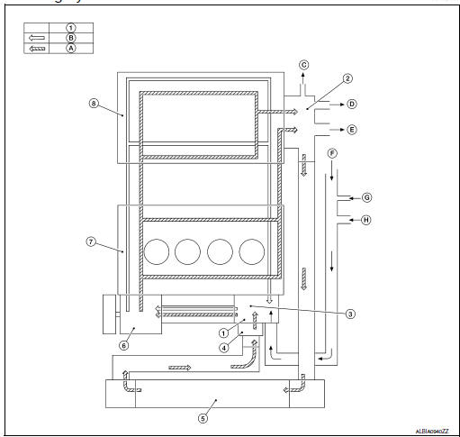
- Thermostat
- Water outlet
- Cylinder block (Thermostat housing)
- Water inlet
- Radiator
- Water pump
- Cylinder block
- Cylinder head
- Open
- Closed
- To electric throttle control actuator
- To oil cooler
- To heater
- From heater
- From electric throttle control actuator
- From oil cooler
Engine Cooling System Schematic
- Radiator
- Water inlet
- Reservoir tank
- Thermostat
- Thermostat housing
- Water pump
- Cylinder head
- Cylinder block
- Water outlet
- Heater
- Oil cooler
- Electric throttle control actuator
- Open
- Closed
 Preparation
Special Service Tool
The actual shape of the tools may differ from those illustrated here.
Tool number
(TechMate No.)
Tool name
Description
KV991J0070
(J-45695-A) ...
 Symptom diagnosis
OVERHEATING CAUSE ANALYSIS
Troubleshooting Chart
...
Other materials:
Basic inspection
DIAGNOSIS AND REPAIR WORKFLOW
Work Flow
OVERALL SEQUENCE
DETAILED FLOW
1.GET INFORMATION FOR SYMPTOM
Get detailed information from the customer about the symptom (the
condition and the environment when
the incident/malfunction occurs).
Check operation condition of the ...
Installing front license plate
Installing front license plate
Use the following steps to mount the front license
plate:
Before mounting the license plate, confirm that
the following parts are enclosed in the plastic
bag:
License plate bracket
License plate bracket (J-nut) screws x 2
License plat ...
The steering switches are inoperative
Description
One or more of the steering switches to control the information display are
inoperative.
Diagnosis Procedure
1.CHECK STEERING SWITCH CIRCUIT
Check steering switch circuit. Refer to MWI-69, "Diagnosis Procedure".
Is the inspection result normal?
YES >> GO TO 2.
...
