Nissan Rogue Service Manual: System
CVT CONTROL SYSTEM
CVT CONTROL SYSTEM : System Description
SYSTEM DIAGRAM
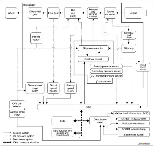
MAIN CONTROL CONTENTS OF TCM
| Controls | Reference |
| Line pressure control | TM-36, "LINE PRESSURE CONTROL : System Description" |
| Shift control | TM-37, "SHIFT CONTROL : System Description" |
| Select control | TM-39, "SELECT CONTROL : System Description" |
| Lock-up control | TM-40, "LOCK-UP CONTROL : System Description" |
| Sport mode control | TM-41, "SPORT MODE CONTROL : System Description" |
| Fail-safe | TM-58, "Fail-safe" |
| Self-diagnosis function | TM-47, "CONSULT Function" |
| Communication function with CONSULT | TM-47, "CONSULT Function" |
LIST OF CONTROL ITEMS AND INPUT/OUTPUT
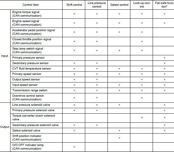
*: If these input/output signals show errors, TCM activates the fail-safe function.
CVT CONTROL SYSTEM : Fail-safe
TCM has a fail-safe mode. The mode functions so that operation can be continued even if the signal circuit of the main electronically controlled input/output parts is damaged.
If the vehicle shows following behaviors including ŌĆ£poor accelerationŌĆØ, a malfunction of the applicable system is detected by TCM and the vehicle may be in a fail-safe mode. At this time, check the DTC code and perform inspection and repair according to the malfunction diagnosis procedures.
Fail-safe function
| DTC | Vehicle behavior | Conditions of vehicle |
| P062F | Not changed from normal driving | ŌĆö |
| P0705 |
|
ŌĆö |
| P0706 |
|
ŌĆö |
| P0711 |
|
Engine coolant temperature when engine start: Temp. Ōēź 10┬░C (50┬░F) |
|
Engine coolant temperature when engine start: ŌłÆ35┬░C (ŌłÆ31┬░F) Ōēż Temp. < 10┬░C (50┬░F) | |
|
Engine coolant temperature when engine star: Temp. < ŌłÆ35┬░C (ŌłÆ31┬░F) | |
| P0712 |
|
Engine coolant temperature when engine start: Temp. Ōēź 10┬░C (50┬░F) |
|
Engine coolant temperature when engine start: ŌłÆ35┬░C (ŌłÆ31┬░F) Ōēż Temp. < 10┬░C (50┬░F) | |
|
Engine coolant temperature when engine star: Temp. < ŌłÆ35┬░C (ŌłÆ31┬░F) | |
| P0713 |
|
Engine coolant temperature when engine start: Temp. Ōēź 10┬░C (50┬░F) |
|
Engine coolant temperature when engine start: ŌłÆ35┬░C (ŌłÆ31┬░F) Ōēż Temp. < 10┬░C (50┬░F) | |
|
Engine coolant temperature when engine star: Temp. < ŌłÆ35┬░C (ŌłÆ31┬░F) | |
| P0715 |
|
ŌĆö |
| P0717 |
|
ŌĆö |
| P0740 |
|
ŌĆö |
| P0743 |
|
ŌĆö |
| P0744 |
|
ŌĆö |
| P0746 |
|
ŌĆö |
| P0776 |
|
When a malfunction occurs on the low oil pressure side |
|
When a malfunction occurs on the high oil pressure side | |
| P0778 |
|
ŌĆö |
| P0779 |
|
ŌĆö |
| P0841 | Not changed from normal driving | ŌĆö |
| P0847 | Not changed from normal driving | ŌĆö |
| P0848 | Not changed from normal driving | ŌĆö |
| P084C | Not changed from normal driving | ŌĆö |
| P084D | Not changed from normal driving | ŌĆö |
| P0863 |
|
ŌĆö |
| P0890 |
|
ŌĆö |
| P0962 |
|
ŌĆö |
| P0963 |
|
ŌĆö |
| P0965 |
|
When a malfunction occurs on the low oil pressure side |
|
When a malfunction occurs on the high oil pressure side | |
| P0966 |
|
ŌĆö |
| P0967 |
|
ŌĆö |
| P2765 |
|
ŌĆö |
| P2813 |
|
When a malfunction occurs on the low oil pressure side |
|
When a malfunction occurs on the high oil pressure side | |
| P2814 | Selector shock is large | ŌĆö |
| P2815 | Selector shock is large | ŌĆö |
| U0073 |
|
ŌĆö |
| U0100 |
|
ŌĆö |
| U0102 | Not changed from normal driving | ŌĆö |
| U0140 | Not changed from normal driving | ŌĆö |
| U0141 | Not changed from normal driving | ŌĆö |
| U0155 | Not changed from normal driving | ŌĆö |
| U0300 |
|
ŌĆö |
| U1000 | Not changed from normal driving | ŌĆö |
| U110F | Not changed from normal driving | ŌĆö |
| U1111 | Not changed from normal driving | ŌĆö |
| U1117 | Not changed from normal driving | ŌĆö |
CVT CONTROL SYSTEM : Protection Control
The TCM becomes the protection control status temporarily to protect the safety when the safety of TCM and transmission is lost. It automatically returns to the normal status if the safety is secured.
The TCM has the following protection control.
CONTROL FOR WHEEL SPIN
| Control | When a wheel spin is detected, the engine output and gear ratio are
limited and the line pressure is increased.
Limits engine output when a wheel spin occurs in any of right and left drive wheels |
| Vehicle behavior in control | If the accelerator is kept depressing during wheel spin, the engine revolution and vehicle speed are limited to a certain degree. |
| Normal return condition | Wheel spin convergence returns the control to the normal control. |
TORQUE IS REDUCED WHEN DRIVING WITH THE REVERSE GEAR
| Control | Engine output is controlled according to a vehicle speed while reversing the vehicle |
| Vehicle behavior in control | Power performance may be lowered while reversing the vehicle. |
| Normal return condition | Torque returns to normal by positioning the selector lever in a range other than ŌĆ£RŌĆØ position |
CONTROL WHEN FLUID TEMPERATURE IS HIGH
| Control | When the CVT fluid temperature is high, the gear shift permission maximum revolution and the maximum torque are reduced than usual to prevent increase of the oil temperature. |
| Vehicle behavior in control | Power performance may be lowered, compared to normal control |
| Normal return condition | The control returns to the normal control when CVT fluid temperature is lowered. |
REVERSE PROHIBIT CONTROL
| Control | The reverse brake is controlled to avoid becoming engaged when the selector lever is set in ŌĆ£RŌĆØ position while driving in forward direction at more than the specified speed. |
| Vehicle behavior in control | If the selector lever is put at ŌĆ£RŌĆØ position when driving with the forward gear, the gear becomes neutral, not reverse. |
| Normal return condition | The control returns to normal control when the vehicle is driven at low speeds. (The reverse brake becomes engaged.) |
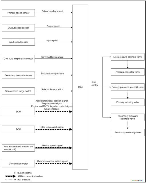
LINE PRESSURE CONTROL
LINE PRESSURE CONTROL : System Description
SYSTEM DIAGRAM
DESCRIPTION
Highly accurate line pressure control and secondary pressure control reduces friction for improvement of fuel economy.
Normal Oil Pressure Control
Appropriate line pressure and secondary pressure suitable for driving condition are determined based on the accelerator pedal position, engine speed, primary pulley (input) speed, secondary pulley (output) speed, vehicle speed, input torque, stop lamp switch signal, transmission range switch signal, lock-up signal, power voltage, target shift ratio, oil temperature, oil pressure, and overdrive control switch signal.
Secondary Pressure Feedback Control
In normal oil pressure control and oil pressure control in shifting, highly accurate secondary pressure is determined by detecting the secondary pressure using an oil pressure sensor and by feedback control.
SHIFT CONTROL
SHIFT CONTROL : System Description
SYSTEM DIAGRAM
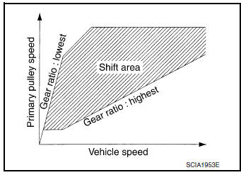
DESCRIPTION
To select the gear ratio that can give the driving force to meet driver's intent or vehicle situation, the vehicle driving condition such as vehicle speed or accelerator pedal position is detected and the most appropriate gear ratio is selected and the shifting method before reaching the speed is determined. The information is output to the primary pressure solenoid valve and secondary pressure solenoid valve to control the line pressure input/output to the pulley, to determine the pulley (movable pulley) position and to control the gear position.
Shift Position Function
- D Position (Normal)
Gear shifting is performed in all shifting ranges from the lowest to the highest gear ratio.
- D Position (O/D OFF)
The gear ratio is generally high by limiting the shifting range on the high side, and this always generates a large driving power.
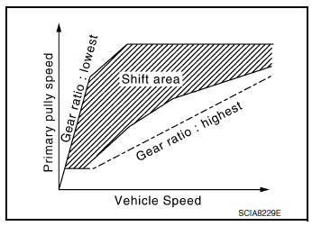
- L Position
By limiting the shifting range only to the lowest of the gear ratio, a large driving force and engine brake are obtained.
Hill Climbing And Descending Control
If a downhill is detected with the accelerator pedal is released, the system performs downshift to increase the engine brake force so that vehicle may not be accelerated more than necessary. If a climbing hill is detected, the system improves the acceleration performance in re-acceleration by limiting the gear shift range on the high side.
NOTE: For engine brake control on a downhill, the control can be stopped with CONSULT.
Control In Acceleration
From change of the vehicle speed or accelerator pedal position, the acceleration request level of the driver or driving scene is evaluated. In start or acceleration during driving, the gear shift characteristics with linearity of revolution increase and vehicle speed increase are gained to improve the acceleration feel.
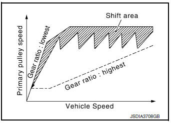
- When the accelerator pedal is depressed 4/8 or more in D position, CVT performs step shifting to allow the vehicle speed and engine speed to increase simultaneously. This improves the feel of acceleration and enables the fuel economy by preventing unnecessary rise in engine speed, compared to the conventional shifting.
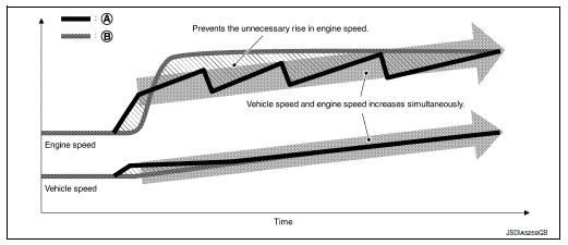
- Step shift
- Conventional shift
SELECT CONTROL
SELECT CONTROL : System Description
SYSTEM DIAGRAM
DESCRIPTION
Based on accelerator pedal angle, engine speed, primary pulley speed, and the input speed, the optimum operating pressure is set to reduce impact of a selector lever operation while shifting from ŌĆ£NŌĆØ (ŌĆ£PŌĆØ) to ŌĆ£DŌĆØ (ŌĆ£RŌĆØ) position.
LOCK-UP CONTROL
LOCK-UP CONTROL : System Description
SYSTEM DIAGRAM
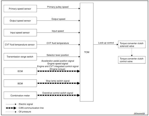
DESCRIPTION
- Controls for improvement of the transmission efficiency by engaging the torque converter clutch in the torque converter and eliminating slip of the converter. Achieves comfortable driving with slip control of the torque converter clutch.
- The oil pressure feed circuit for the torque converter clutch piston chamber is connected to the torque converter clutch control valve. The torque converter clutch control valve is switched by the torque converter clutch solenoid valve with the signal from TCM. This controls the oil pressure circuit, which is supplied to the torque converter clutch piston chamber, to the release side or engagement side.
- If the CVT fluid temperature is low or the vehicle is in fail-safe mode due to malfunction, lock-up contro
Lock-up engagement
In lock-up engagement, the torque converter clutch solenoid valve makes the torque converter clutch control valve locked up to generate the lock-up apply pressure. This pushes the torque converter clutch piston for engagement.
Lock-up release condition
In lock-up release, the torque converter clutch solenoid valve makes the torque converter clutch control valve non-locked up to drain the lock-up apply pressure. This does not engage the torque converter clutch piston.
SPORT MODE CONTROL
SPORT MODE CONTROL : System Description
SYSTEM DIAGRAM
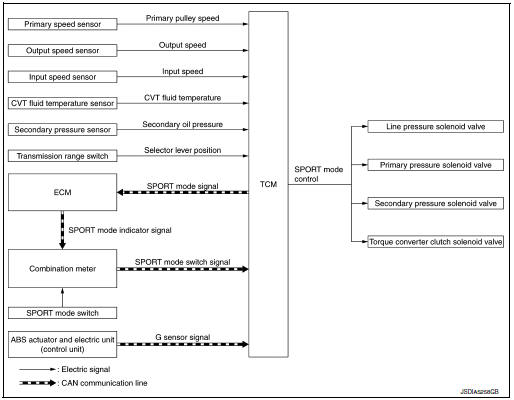
DESCRIPTION
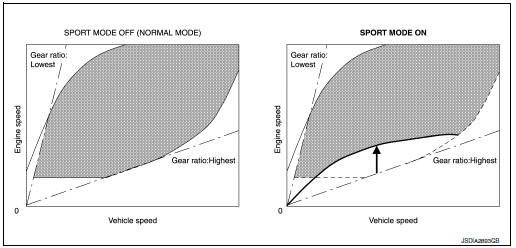
- For a sporty driving on winding roads, establishing sport mode allows the driver to perform a sporty driving different from normal driving performed in D position.
- If overdrive control switch is operated during SPORT mode ON condition, overdrive control operation will take priority.
Sport Mode Function
High Gear Ratio Limit
- Engine speed is kept higher than at D position driving, which helps to operate a ŌĆ£sportyŌĆØ driving.
Step Shift
- Pressing down the accelerator pedal allows to drive the vehicle with a feeling of A/T-like gear shifting.
Braking Down Shift
- At a moderate braking operation before corner etc., the engine speed increases according to the deceleration and the transmission shifts down automatically, in order to optimize the response at reacceleration while providing an adequate engine braking.

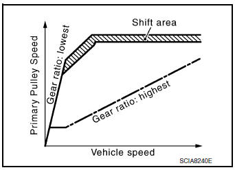
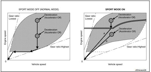
Acceleration Off Ratio Hold
- When the vehicle is decelerated by quickly releasing the foot from
accelerator pedal, transmission does not
shift up automatically to keep a constant gear ratio, holding the high
engine speed.
When the vehicle is decelerated (by accelerator pedal OFF) in upper area of double line in below chart, the engine speed shows a characteristic like ŌĆ£AŌĆØ.
On the other hand, when the vehicle is decelerated (by accelerator pedal OFF) in lower area of double line in below chart, the engine speed shows a characteristic like ŌĆ£BŌĆØ.
Fail-Safe
If a malfunction occurs in CVT system during SPORT mode ON, SPORT mode indicator extinguishes and the vehicle returns to standard D position driving.
WARNING/INDICATOR/CHIME LIST
WARNING/INDICATOR/CHIME LIST : Warning Lamp/Indicator Lamp
| Name | Design | Arrangement/Function |
| O/D OFF indicator lamp |
|
Regarding the arrangement. Refer to MWI-7, "METER SYSTEM : Design". |
| Regarding the function. Refer to TM-19, "CVT CONTROL SYSTEM : O/D OFF Indicator Lamp". | ||
| Malfunction indicator lamp (MIL) |
 |
Regarding the arrangement. Refer to MWI-7, "METER SYSTEM : Design". |
| Regarding the function. Refer to EC-49, "WARNING/INDICATOR/CHIME LIST : Malfunction Indicator Lamp (MIL)". | ||
| Sport mode indicator lamp |
 |
Regarding the arrangement. Refer to MWI-7, "METER SYSTEM : Design". |
| Regarding the function. Refer to DMS-4, "SPORT Mode Indicator Lamp". |

 Structure and operation
TRANSAXLE
TRANSAXLE : Cross-Sectional View
Converter housing
Oil pump
Planetary gear
Control valve
Oil pan
Steel belt
Primary pulley
Secondary pulley
Side cover
Transa ...
 On board diagnostic (OBD) system
Diagnosis Description
This system is an on board diagnostic system that records exhaust
emission-related diagnostic information
and detects a sensors/actuator-related malfunction. A malfunction is ...
Other materials:
Removal and installation
FRONT COMBINATION LAMP
Exploded View
Front fender
Front combination lamp
Clip
Removal and Installation
REMOVAL
Remove front bumper fascia. Refer to EXT-17, "Removal and
Installation".
Remove front combination lamp bolts and clip.
Pull front c ...
Component parts
Component Parts Location
No.
Component
Function
1
Key switch
Transmits the key switch signal to the BCM.
Refer to SEC-115, "Component Parts Location" (without Intelligent Key
system) for detailed installation
location.
2
...
Information display (ASCD)
Component Function Check
1.CHECK INFORMATION DISPLAY
Start engine.
Press ASCD MAIN switch on ASCD steering switch.
Drive the vehicle at more than 40 km/h (25 MPH).
CAUTION:
Always drive vehicle at a safe speed.
Press SET/− switch.
Check that the r ...
