Nissan Rogue Service Manual: Steering gear and linkage
Exploded View
REMOVAL AND INSTALLATION
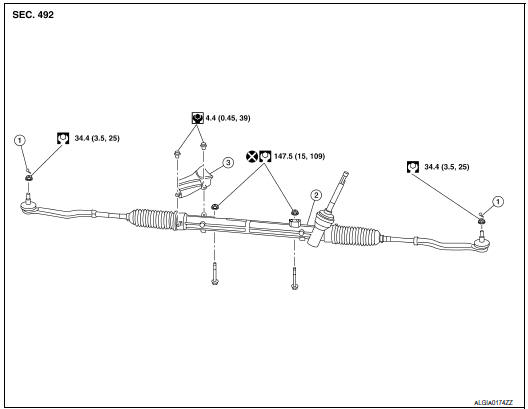
- Cotter pin
- Steering gear
- Heat shiel
Removal and Installation
REMOVAL
- Set the front wheels and tires to the straight-ahead position.
- Remove the floor cover. Refer to ST-12, "Exploded View".
- Remove the floor seal. Refer to ST-12, "Exploded View".
- Remove the joint retaining bolt and separate the steering column
yoke from the steering gear pinion shaft.
Refer to ST-12, "Exploded View".
- Remove the cotter pins (LH/RH), nuts (LH/RH) and disconnect the outer sockets (LH/RH).
- Separate the stabilizer connecting rods (LH/RH) from the stabilizer bar. Refer to FSU-20, "Exploded View".
- Disconnect the harness connector for oxygen sensor 2. Refer to EX-5, "Exploded View"
- Remove the front exhaust tube. Refer to EX-5, "Exploded View".
- Remove the center exhaust tube. Refer to EX-5, "Exploded View".
- . Remove the lower torque rod. Refer to EM-81, "Exploded View".
- . Remove front suspension member stay and support the front suspension using a suitable jack. Refer to FSU-20, "Exploded View".
- Remove bolts and remove the steering gear.
INSTALLATION
Installation is in the reverse order of removal.
CAUTION:
- With the steering linkage disconnected, the spiral cable may snap by turning the steering wheel beyond the limited number of turns.
- When connecting the steering column yoke (1) to the steering gear pinion shaft (2), be sure that gap (A) lines up with the joint retaining bolt hole.
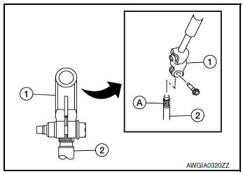
- When installing the steering column, finger-tighten all of the lower bracket and joint retaining bolts; then tighten them to specification. Do not apply undue stress to the steering column.
- Do not reuse steering gear nuts.
- Check wheel alignment. Refer to FSU-7, "Inspection".
- Adjust the neutral position of the steering angle sensor. Refer to BRC-70, "Work Procedure".
Inspection
INSPECTION AFTER INSTALLATION
- Check if steering wheel turns smoothly when it is turned several times fully to the end of the left and right.
- Check the steering wheel play, neutral position steering wheel, steering wheel turning force, and front wheel turning angle. Refer to ST-7, "Inspection".
 Steering column
Exploded View
Steering column
Floor cover
Floor seal
Removal and Installation
CAUTION:
Any time the ignition switch has been disconnected, removed or
install ...
 Unit disassembly and assembly
STEERING GEAR AND LINKAGE
Exploded View
DISASSEMBLY AND ASSEMBLY
Steering gear
Inner boot clamp
Boot
Outer boot clamp
Outer socket
Disassembly and Assem ...
Other materials:
Removal and installation
IPDM E/R (INTELLIGENT POWER DISTRIBUTION MODULE ENGINE
ROOM)
Exploded View
IPDM E/R cover
IPDM E/R
IPDM E/R case
IPDM E/R harness cover A
IPDM E/R harness cover B
Front
Removal and Installation
CAUTION: IPDM E/R integrated relays are not serviceable
parts, do not ...
Compression pressure
CHECKING COMPRESSION PRESSURE
Warm up the engine to full operating temperature.
Release the fuel pressure. Refer to EC-144, "Work Procedure".
Remove the ignition coil and spark plug from each cylinder. Refer
to EM-36, "Removal and Installation"
and ...
C1101, C1102, C1103, C1104 wheel sensor
DTC Logic
DTC DETECTION LOGIC
DTC
Display Item
Malfunction detected condition
Possible causes
C1101
RR RH SENSOR-1
When power supply voltage of rear wheel sensor
RH is low.
When an open or shorted circuit is detected in rear
wheel sensor RH ...
