Nissan Rogue Service Manual: Removal and installation
GENERATOR
Exploded View
REMOVAL
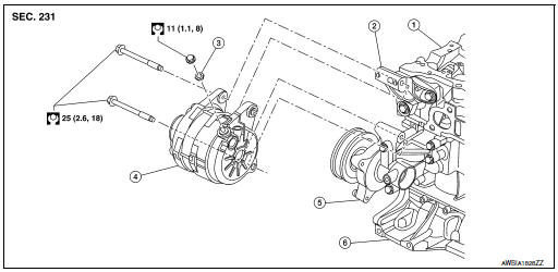
- Cylinder head
- Generator bracket
- Washer
- Generator
- Water pump
- Cylinder block
Removal and Installation
REMOVAL
- Disconnect negative terminal from battery. Refer to PG-75, "Exploded View".
- Remove wheel and tire (RH) using a power tool. Refer to WT-60, "Removal and Installation".
- Remove fender protector side cover. Refer to EXT-28, "FENDER PROTECTOR : Exploded View"
- Remove front air spoiler. Refer to EXT-16, "Exploded View".
- Remove engine under cover. Refer to EXT-37, "ENGINE UNDER COVER : Removal and Installation".
- Remove drive belt. Refer to EM-13, "Removal and Installation".
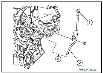
- Remove oil level gauge (1).
- Remove oil level gauge guide (2).
- Remove oil level gauge guide O-ring (3).
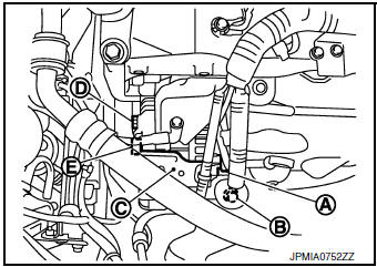
- Disconnect generator connector (A).
- Remove “B” terminal nut (B) and “B” terminal harness.
- Remove harness bracket (C).
NOTE: Harness ground does not have to be removed during bracket removal.
- Remove upper generator mounting bolt (D), using suitable tool.
- Remove lower generator mounting bolt (E), using suitable tool.
- Remove generator upward from the vehicle.
INSTALLATION
Installation is in the reverse order of removal.
- Tighten oil level gauge guide bolt to specification.
Oil level gauge guide bolt : 21.6 N·m (2.2 kg-m, 16 ft-lb)
CAUTION:
- Be careful to tighten “B” terminal nut carefully.
- Install generator and check tension of belt. Refer to EM-13, "Checking".
- Do not reuse oil level gauge guide O-ring.
- Prior to installation, apply clean engine oil to oil level gauge guide O-ring.
- Ensure O-ring sealing surface is free from dust or imprefections.
- Allow engine to run for 5 minutes and inspect for engine oil leaks.
Inspection
GENERATOR PULLEY INSPECTION
Perform the following.
- Make sure that the generator pulley does not bind or rattle.
- Make sure that the generator pulley is tight. Refer to CHG-20, "Exploded View".
 Symptom diagnosis
CHARGING SYSTEM
Symptom Table
...
 Service data and specifications (SDS)
Generator
...
Other materials:
EVAP control system pressure sensor
Exploded View
EVAP control system pressure sensor
O-ring
EVAP canister
EVAP canister vent control valve
EVAP canister vent control valve hose
EVAP vent line
EVAP canister purge hose
Clamp
Front
Removal and Installation
NOTE:
The EVAP canister syst ...
Preparation
Special Service Tool
The actual shapes of tools may differ from those illustrated here.
Tool number
(TechMate No.)
Tool name
Description
—
(J-46534)
Trim Tool Set
Removing trim components
Commercial Service Tool
(TechMate No.)
Tool n ...
Precaution
Precaution for Supplemental Restraint System (SRS) "AIR BAG" and "SEAT
BELT
PRE-TENSIONER"
The Supplemental Restraint System such as “AIR BAG” and “SEAT BELT PRE-TENSIONER”,
used along
with a front seat belt, helps to reduce the risk or severity of injury to the
...
